YVF2 Series Variable Speed Motors
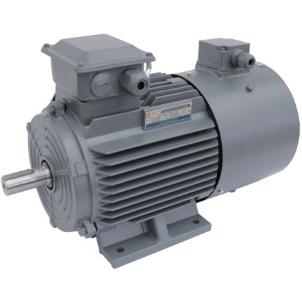
YVF2 Series Variable Speed Motors are AC high efficiency, energy saving motors. It can be configured with the frequency converter from domastic and abroad. It has the characteristics with reliable operation and easy maintenance. Separate axial-flow ventilator is installed, which can guarantee a better cooling effect in different speed. YVF2 series motors can be widely applied to the equipment which need speed control in light industry, textile, chemical, metallurgy and machine tool industries etc.
- Rated output:0.55 ~ 315 kW
- Frame Size:80 ~ 355
- Rated voltage:380 V
- Cooling method:IC416
- Protection degree:IP55
- Insulation class:F
- Coolant temperature:-15 ~ 40 ºC
- Site altitude:Up to 1000 m above sea level
Construction and mounting type
| Construction type | With feet and without flange on the end-shield (DE) | ||||||||
|---|---|---|---|---|---|---|---|---|---|
| Mounting type | IM B3FS3) 80 ~ 355 | IM B6FS 80 ~ 160 | IM B7FS80 ~ 160 | IM B8FS 80 ~ 160 | IM V5 1)FS 80 ~ 160 | IM V6 2)FS 80 ~ 160 | |||
| Diagram |  |
 |
 |
 |
 |
 |
|||
| Construction type | Without feet and with flange on the end-shield (DE) | With feet and with flange on the end-shield (DE) | |||||||
| Mounting type | IM B5FS 80 ~ 280 | IM V1 1)FS 80 ~ 355 | IM V3 2)FS 80 ~ 160 | IM B35FS 80 ~ 355 | IM V15 1)FS 80 ~ 160 | IM V35 2)FS 80 ~ 160 | |||
| Diagram |  |
 |
 |
|
|
|
|||
| Construction type | Without feet and with C-flange on the end-shield (DE) | With feet and with C-flange on the end-shield (DE) | |||||||
| Mounting type | IM B14FS 80 ~ 112 | IM V18 1)FS 80 ~ 112 | IM V19 2)FS 80 ~ 112 | IM B34FS80 ~ 112 | |||||
| Diagram |  |
 |
 |
|
|||||
- Note:
- 1) At outdoor application, the using of protective cover (Option code H00) isrecommended
- 2) At out door application the protection of shaft again jet-water is recommended
- 3) FS-frame size
Order No. example
- Foot notes:
- 1) Order other voltages with voltage code 90 and the corresponding Option code (see under "Option") .
- 2) The type of mounting construction is stamped on the rating plate.
- 3) For motor with IM B5, IM V1, IM V3, IM B14, IM V18 and IM V19 construction and mounting type, the 16th digit of motor order No. must be "4";
- 4) Only for FS80 ~ 112.
- 5) Choose this option, the connection box will be changed to cast iron.
- 6) Only applicable for frame size 100-355.
- 7) Please specially consult with Siemens.
Variable Speed Motors
4 pole, 5.5 kW, IM B3, 380VY 50 Hz, IP55,
connection box at right side and cable entry at bottom (view from DE) Motor order code: YVF2-132S-4-5.5-2-1AA5
Nameplate example
Bearing system
YVF2 series motors are supplied with the ball bearing as standard. These bearings are either of the sealed or regreasable type.
For FS80 ~ 160, the floating bearings are assembled; for FS180 ~ 355, floating bearing at DE, and fixed bearing at NDE assembled.
| Frame size | Pole | DE bearing | NDE bearing (Horizontal mounting) | NDE bearing (Horizontal mounting) |
|---|---|---|---|---|
| 80 | 2、4、6 | 6204 2RZ C3 | 6204 2RZ C3 | 6204 2RZ C3 |
| 90 | 2、4、6 | 6205 2RZ C3 | 6205 2RZ C3 | 6205 2RZ C3 |
| 100 | 2、4、6 | 6206 2RZ C3 | 6206 2RZ C3 | 6206 2RZ C3 |
| 112 | 2、4、6 | 6206 2RZ C3 | 6206 2RZ C3 | 6206 2RZ C3 |
| 132 | 2、4、6、8 | 6208 2RZ C3 | 6208 2RZ C3 | 6208 2RZ C3 |
| 160 | 2、4、6、8 | 6309 2RZ C3 | 6209 2RZ C3 | 6209 2RZ C3 |
| 180 | 2、4、6、8 | 6310 C3 | 6210 C3 | 6210 C3 |
| 200 | 2、4、6、8 | 6312 C3 | 6212 C3 | 6212 C3 |
| 225 | 2、4、6、8 | 6313 C3 | 6213 C3 | 6213 C3 |
| 250 | 2、4、6、8 | 6314 C3 | 6215 C3 | 7215 AC |
| 280 | 2、4、6、8 | 6317 C3 | 6217 C3 | 7217 AC |
| 2 | 6319 C3 | 6317 C3 | 7317 AC | |
| 4、6、8 | 6319 C3 | 6319 C3 | 7319 AC | |
| 2 | 6319 C3 | 6319 C3 | 7319 AC | |
| 4、6、8 | 6322 C3 | 6322 C3 | 7322 AC |
| Frame size | Pole | Constant Torque | Constant Power |
|---|---|---|---|
| FS80~180 | 2P | 3~50 | 50~100 |
| FS200~355 | 50~60 | ||
| FS80~315 | 4P | 50~100 | |
| FS355 | 50~75 | ||
| FS80~FS355 | 6P | 50~100 | |
| FS80~FS355 | 8P |
| Frame size | Contact screw thread | Outer cable diameter (sealing range) (mm) | Cable entry size |
|---|---|---|---|
| 80 ~ 100 | M4 | 10~14 | M24 x 1.5 |
| 112 ~ 132 | M5 | 13~18 | M27 x 2 + M27 x 2 |
| 160 ~ 180 | M5 | 18~25 | M36 x 2 + M36 x 2 |
| 200 ~ 225 | M8 | 22~32 | M48 x 2 + M48 x 2 |
| 250 | M10 | 37~44 | M64 x 2 + M64 x 2 |
| 280 | M10 | ||
| 315 | M12 | ||
| 355 | M16 | 45~52 | M72 x 2 + M72 x 2 |
| Motor frame size | Rated voltage(V) | Rated frequency(Hz) | Rated output(W) | Current(A) | Speed(r/min) | ΔL |
|---|---|---|---|---|---|---|
| 80 | 220D/380Y | 50 | 30 | 0.14/0.08 | 2800 | 60 |
| 90 | 220D/380Y | 50 | 30 | 0.14/0.08 | 2800 | 75 |
| 100 | 220D/380Y | 50 | 52 | 0.21/0.12 | 2800 | 70 |
| 112 | 220D/380Y | 50 | 52 | 0.21/0.12 | 2800 | 80 |
| 132 | 220D/380Y | 50 | 45 | 0.35/0.2 | 1400 | 75 |
| 160 | 220D/380Y | 50 | 45 | 0.35/0.2 | 1400 | 45 |
| 180 | 220D/380Y | 50 | 120 | 1.04/0.6 | 1400 | 55 |
| 200 | 220D/380Y | 50 | 120 | 1.04/0.6 | 1400 | 60 |
| 225 | 220D/380Y | 50 | 120 | 1.04/0.6 | 1400 | 70 |
| 250 | 220D/380Y | 50 | 230 | 1.73/1.0 | 1400 | 65 |
| 280 | 220D/380Y | 50 | 300 | 1.8/1.2 | 1400 | 105 |
| 315 | 220D/380Y | 50 | 1100 | 4.33/2.5 | 1350 | 145 |
| 355 | 220D/380Y | 50 | 1100 | 4.33/2.5 | 1350 | 150 |
Note: The fan can be running with supply 210 ~ 240VD/360 ~ 420VY 50Hz, and also 220 ~ 260VD/380 ~ 480VY 60Hz. Other voltage supply, possible on request.
Technical data
| Power(kW) | Type | Rated torque(N.m) | Current(A) | Weight(kG) | Type | Rated torque(N.m) | Current(A) | Weight(kG) | Power of suited converter(kW) |
|---|---|---|---|---|---|---|---|---|---|
| 0.55 | YVF2-80M2-6 | 5.3 | 1.66 | 16.0 | 1 | ||||
| 0.75 | YVF2-90S-6 | 7.2 | 2.25 | 20 | 1 | ||||
| 1.1 | YVF2-90L-6 | 10.5 | 3.2 | 24 | 2 | ||||
| 1.5 | YVF2-100L-6 | 14.3 | 4.2 | 31 | 2 | ||||
| 2.2 | YVF2-112M-6 | 21 | 6 | 41 | YVF2-132S-8 | 28 | 7.5 | 72 | 3 |
| 3 | YVF2-132S-6 | 28.6 | 7.9 | 54 | YVF2-132M-8 | 38.2 | 9.9 | 70 | 4 |
| 4 | YVF2-132M1-6 | 38.2 | 10.1 | 65 | YVF2-160M1-8 | 51 | 11.6 | 105 | 6 |
| 5.5 | YVF2-132M2-6 | 52.5 | 13.4 | 73 | YVF2-160M2-8 | 70 | 15.1 | 103 | 10 |
| 7.5 | YVF2-160M-6 | 71.6 | 17.2 | 115 | YVF2-160L-8 | 95.5 | 20.5 | 127 | 10 |
| 11 | YVF2-160L-6 | 105 | 24.5 | 145 | YVF2-180L-8 | 140 | 26 | 163 | 15 |
| 15 | YVF2-180L-6 | 143 | 31.5 | 183 | YVF2-200L-8 | 191 | 34 | 233 | 20 |
| 18.5 | YVF2-200L1-6 | 177 | 39.5 | 235 | YVF2-225S-8 | 236 | 42 | 246 | 30 |
| 22 | YVF2-200L2-6 | 210 | 46.5 | 252 | YVF2-225M-8 | 280 | 50 | 286 | 30 |
| 30 | YVF2-225M-6 | 287 | 62 | 320 | YVF2-250M-8 | 382 | 64 | 355 | 40 |
| 37 | YVF2-250M-6 | 353 | 75 | 400 | YVF2-280S-8 | 471 | 84 | 427 | 50 |
| 45 | YVF2-280S-6 | 430 | 88 | 483 | YVF2-280M-8 | 573 | 97 | 485 | 60 |
| 55 | YVF2-280M-6 | 525 | 106 | 550 | YVF2-315S-8 | 700 | 115 | 665 | 70 |
| 75 | YVF2-315S-6 | 716 | 146 | 790 | YVF2-315M-8 | 955 | 156 | 845 | 100 |
| 90 | YVF2-315M-6 | 859 | 173 | 950 | YVF2-315L1-8 | 1146 | 182 | 890 | 120 |
| 110 | YVF2-315L1-6 | 1050 | 210 | 1085 | YVF2-315L2-8 | 1401 | 220 | 1040 | 150 |
| 132 | YVF2-315L2-6 | 1261 | 250 | 1125 | YVF2-355M1-8 | 1681 | 265 | 1530 | 180 |
| 160 | YVF2-355M1-6 | 1528 | 300 | 1770 | YVF2-355M2-8 | 2037 | 325 | 1650 | 210 |
| 185 | YVF2-355M2-6 | 1767 | 350 | 1770 | YVF2-355L1-8 | 2356 | 365 | 1820 | 220 |
| 200 | YVF2-355M3-6 | 1910 | 375 | 1810 | YVF2-355L2-8 | 2547 | 395 | 1930 | 270 |
| 220 | YVF2-355L1-6 | 2101 | 415 | 1980 | 280 | ||||
| 250 | YVF2-355L2-6 | 2387 | 470 | 2010 | 350 |
Type of construction IM B3
Type of construction IM B35

| Frame size | Type YVF2- | pols | Dimension designation according to IEC standards | |||||||||
|---|---|---|---|---|---|---|---|---|---|---|---|---|
| A | AA | AB | AC | AD / AD' | AF / AF' | AG | AH | AS | B | |||
| 80 M | 80M1-□80M2-□ | 2,4, 6 | 125125 | 3434 | 160160 | 161161 | 145145 | 107107 | 130130 | -- | 5252 | 100100 |
| 90 S | 90S-□ | 2, 4, 6 | 140 | 36 | 180 | 175 | 160 | 116 | 135 | - | 55 | 100 |
| 90 L | 90L-□ | 140 | 36 | 180 | 175 | 160 | 116 | 135 | - | 55 | 125 | |
| 100 L | 100L-2100L1-4100L-6100L2-4 | 2464 | 160160 | 4040 | 200200 | 196196 | 165165 | 129129 | 135135 | -- | 5555 | 140140 |
| 112 M | 112M-□ | 2, 4, 6 | 190 | 45 | 226 | 217 | 193 | 145 | 152 | - | 64 | 140 |
| 132 S | 132S1-2 | 2, | 216 | 55 | 262 | 258 | 203 | 166 | 152 | - | 64 | 140 |
| 132S-□ | 4, 6, 8 | |||||||||||
| 132S2-2 | 2 | 216 | 55 | 262 | 258 | 203 | 166 | 152 | - | 64 | 140 | |
| 132 M | 132M-4 | 4 | 216 | 55 | 262 | 258 | 203 | 166 | 152 | - | 64 | 178 |
| 132M1-6 | 6 | |||||||||||
| 132M-8 | 8 | |||||||||||
| 132M2-6 | 6 | 216 | 55 | 262 | 258 | 203 | 166 | 152 | - | 64 | 178 | |
| 160 M | 160M1-2 | 2 | 254 | 65 | 314 | 311 | 255 | 207 | 195 | 480 | 83 | 210 |
| 160M-4 | 4 | |||||||||||
| 160M-6 | 6 | |||||||||||
| 160M1-8 | 8 | |||||||||||
| 160M2-□ | 2, 8 | 254 | 65 | 314 | 311 | 255 | 207 | 195 | 480 | 83 | 210 | |
| 160 L | 160L-□ | 2, 4, 6 | 254 | 65 | 314 | 311 | 255 | 207 | 195 | 480 | 83 | 254 |
| 8 | ||||||||||||
Type of construction IM B5 and IM V1
Type of construction IM B14
| Dimension designation according to IEC standards | DE shaft extensiion | ||||||||||||||||
|---|---|---|---|---|---|---|---|---|---|---|---|---|---|---|---|---|---|
| BB | BC | BE | C | H | h | HA | HH | K / K' | L | LL | D | DB | E | EB | F | GA | |
| 130 | 15 | - | 50 | 80 | 29 | 10 | 72 | 10 | 350 | 103 | 19 | M6 | 40 | 22 | 6 | 21.5 | |
| 130 | 15 | - | 50 | 80 | 29 | 10 | 72 | 10 | 350 | 103 | 19 | M6 | 40 | 22 | 6 | 21.5 | |
| 140 | 20 | - | 56 | 90 | 35 | 12 | 75 | 10 | 395 | 110 | 24 | M8 | 50 | 32 | 8 | 27 | |
| 165 | 20 | - | 56 | 90 | 35 | 12 | 75 | 10 | 420 | 110 | 24 | M8 | 50 | 32 | 8 | 27 | |
| 188 | 24 | - | 63 | 100 | 45 | 14 | 77 | 12 | 455 | 110 | 28 | M10 | 60 | 40 | 8 | 31 | |
| 188 | 24 | - | 63 | 100 | 45 | 14 | 77 | 12 | 455 | 110 | 28 | M10 | 60 | 40 | 8 | 31 | |
| 180 | 20 | 42 | 70 | 112 | 48 | 15 | 87 | 12 | 480 | 119 | 28 | M10 | 60 | 40 | 8 | 31 | |
| 186 | 23 | 42 | 89 | 132 | 68 | 18 | 99 | 12 | 545 | 119 | 38 | M12 | 80 | 56 | 10 | 41 | |
| 186 | 23 | 42 | 89 | 132 | 68 | 18 | 99 | 12 | 545 | 119 | 38 | M12 | 80 | 56 | 10 | 41 | |
| 224 | 23 | 42 | 89 | 132 | 68 | 18 | 99 | 12 | 585 | 119 | 38 | M12 | 80 | 56 | 10 | 41 | |
| 224 | 23 | 42 | 89 | 132 | 68 | 18 | 99 | 12 | 585 | 119 | 38 | M12 | 80 | 56 | 10 | 41 | |
| 260 | 25 | 60 | 108 | 160 | 77 | 20 | 150 | 15 | 660 | 157 | 42 | M16 | 110 | 80 | 12 | 45 | |
| 260 | 25 | 60 | 108 | 160 | 77 | 20 | 150 | 15 | 660 | 157 | 42 | M16 | 110 | 80 | 12 | 45 | |
| 320 | 25 | 60 | 108 | 160 | 77 | 20 | 150 | 15 | 720 | 157 | 42 | M16 | 110 | 80 | 12 | 45 | |
| 304 | 705 | ||||||||||||||||
| Frame size | Type YVF2- | pols | Dimension designation according to IEC standards | |||||||||
|---|---|---|---|---|---|---|---|---|---|---|---|---|
| A | AA | AB | AC | AD / AD' | AF / AF' | AG | AH | AS | B | |||
| 180M | 180M-□ | 2,4 | 279 | 70 | 349 | 356 | 275 | 223 | 195 | 515 | 83 | 241 |
| 180L | 180L-□ | 4,6 | 279 | 70 | 349 | 356 | 275 | 223 | 195 | 515 | 83 | 279 |
| 8 | ||||||||||||
| 200L | 200L1-2 | 2 | 318 | 70 | 388 | 398 | 310 | 248 | 255 | 575 | 107 | 305 |
| 200L-4 | 4 | |||||||||||
| 200L1-6 | 6 | |||||||||||
| 200L2-2 | 2 | 318 | 70 | 388 | 398 | 310 | 248 | 255 | 575 | 107 | 305 | |
| 200L2-6 | 6 | |||||||||||
| 200L-8 | 8 | |||||||||||
| 225S | 225S-4 | 4 | 356 | 75 | 431 | 428 | 325 | 257 | 255 | 605 | 107 | 286 |
| 225S-8 | 8 | |||||||||||
| 225M | 225M-2 | 2 | 356 | 75 | 431 | 428 | 325 | 257 | 255 | 605 | 107 | 311 |
| 225M-□ | 4, 6 | 356 | 75 | 431 | 428 | 325 | 257 | 255 | 605 | 107 | 311 | |
| 225M-8 | 8 | 356 | 75 | 431 | 428 | 325 | 257 | 255 | 605 | 107 | 311 | |
| 250M | 250M-2250M-□250M-8 | 24, 68 | 406406 | 8080 | 484484 | 475475 | 360360 | 292292 | 285285 | 670670 | 124124 | 349349 |
| 280S | 280S-2 | 2 | 457 | 85 | 542 | 530 | 395 | 322 | 285 | 755 | 124 | 368 |
| 280S-□ | 4, 6 | 457 | 85 | 542 | 530 | 395 | 322 | 285 | 755 | 124 | 368 | |
| 280S-8 | 8 | |||||||||||
| 280M | 280M-2 | 2 | 457 | 85 | 542 | 530 | 395 | 322 | 285 | 755 | 124 | 419 |
| 280M-□ | 4, 6 | 457 | 85 | 542 | 530 | 395 | 322 | 285 | 755 | 124 | 419 | |
| 280M-8 | 8 | 457 | 85 | 542 | 530 | 395 | 322 | 285 | 755 | 124 | 419 | |
| 315S | 315S-2 | 2 | 508 | 120 | 628 | 581 | 505 | 413 | 370 | 920 | 171 | 406 |
| 315S-□ | 4,6 | |||||||||||
| 315S-8 | 8 | 508 | 120 | 628 | 581 | 505 | 413 | 370 | 920 | 171 | 406 | |
| 315M | 315M-2 | 2 | 508 | 120 | 628 | 581 | 505 | 413 | 370 | 920 | 171 | 457/508 |
| 315M-□ | 4, 6 | |||||||||||
| 315M-8 | 8 | 508 | 120 | 628 | 581 | 505 | 413 | 370 | 920 | 171 | 457/508 | |
| 315L | 315L1-2 | 2 | 508 | 120 | 628 | 581 | 505 | 413 | 370 | 920 | 171 | 457/508 |
| 315L-2 | 2 | |||||||||||
| 315L2-2 | 2 | |||||||||||
| 315L1-4 | 4 | 508 | 120 | 628 | 581 | 505 | 413 | 370 | 920 | 171 | 457/508 | |
| 315L-4 | 4 | |||||||||||
| 315L2-4 | 4 | |||||||||||
| 315L1-6 | 6 | |||||||||||
| 315L2-6 | 6 | |||||||||||
| 315L1-8 | 8 | 508 | 120 | 628 | 581 | 505 | 413 | 370 | 920 | 171 | 457/508 | |
| 315L2-8 | 8 | |||||||||||
| 355M | 355M1-2 | 2 | 610 | 120 | 730 | 698 | 625 | 517 | 454 | 1145 | 181 | 560/630 |
| 355M1-□ | 4,6,8 | 610 | 120 | 730 | 698 | 625 | 517 | 454 | 1145 | 181 | 560/630 | |
| 355M2-2 | 2 | 610 | 120 | 730 | 698 | 625 | 517 | 454 | 1145 | 181 | 560/630 | |
| 355M2-□ | 4,6 | |||||||||||
| 355M2-8 | 8 | 610 | 120 | 730 | 698 | 625 | 517 | 454 | 1145 | 181 | 560/630 | |
| 355M3-6 | 6 | 610 | 120 | 730 | 698 | 625 | 517 | 454 | 1145 | 181 | 560/630 | |
| 355L | 355L1-2 | 2 | 610 | 120 | 730 | 698 | 625 | 517 | 454 | 1145 | 181 | 560/630 |
| 355L1-□ | 4, 6 | |||||||||||
| 355L1-8 | 8 | 610 | 120 | 730 | 698 | 625 | 517 | 454 | 1145 | 181 | 560/630 | |
| 355L-2 | 2 | 610 | 120 | 730 | 698 | 625 | 517 | 454 | 1145 | 181 | 560/630 | |
| 355L2-□ | 4, 6 | 610 | 120 | 730 | 698 | 625 | 517 | 454 | 1145 | 181 | 560/630 | |
| 355L2-8 | 8 | |||||||||||
| Dimension designation according to IEC standards | DE shaft extensiion | ||||||||||||||||
|---|---|---|---|---|---|---|---|---|---|---|---|---|---|---|---|---|---|
| BB | BC | BE | C | H | h | HA | HH | K / K' | L | LL | D | DB | E | EB | F | GA | |
| 345 | 35 | 60 | 121 | 180 | 97 | 22 | 161 | 15 | 785 | 157 | 48 | M16 | 110 | 80 | 14 | 51.5 | |
| 385 | 35 | 60 | 121 | 180 | 97 | 22 | 161 | 15 | 825 | 157 | 48 | M16 | 110 | 80 | 14 | 51.5 | |
| 344 | 785 | ||||||||||||||||
| 412 | 32 | 72 | 133 | 200 | 94 | 25 | 186 | 19 | 880 | 194 | 55 | M20 | 110 | 80 | 16 | 59 | |
| 412 | 32 | 72 | 133 | 200 | 94 | 25 | 186 | 19 | 880 | 194 | 55 | M20 | 110 | 80 | 16 | 59 | |
| 379 | 845 | ||||||||||||||||
| 366 | 45 | 72 | 149 | 225 | 119 | 28 | 189 | 19 | 880 | 194 | 60 | M20 | 140 | 100 | 18 | 64 | |
| 880 | |||||||||||||||||
| 405 | 45 | 72 | 149 | 225 | 119 | 28 | 189 | 19 | 905 | 194 | 55 | M20 | 110 | 80 | 16 | 59 | |
| 405 | 45 | 72 | 149 | 225 | 119 | 28 | 189 | 19 | 935 | 194 | 60 | M20 | 140 | 100 | 18 | 64 | |
| 391 | 45 | 72 | 149 | 225 | 119 | 28 | 189 | 19 | 905 | 194 | 60 | M20 | 140 | 100 | 18 | 64 | |
| 460 | 40 | 80 | 168 | 250 | 126 | 30 | 222 | 24 | 1020 | 224 | 60 | M20 | 140 | 100 | 18 | 64 | |
| 460 | 40 | 80 | 168 | 250 | 126 | 30 | 222 | 24 | 1020 | 224 | 65 | M20 | 140 | 100 | 18 | 69 | |
| 425 | 970 | ||||||||||||||||
| 485 | 74 | 80 | 190 | 280 | 156 | 35 | 216 | 24 | 1090 | 224 | 65 | M20 | 140 | 100 | 18 | 69 | |
| 485 | 74 | 80 | 190 | 280 | 156 | 35 | 216 | 24 | 1090 | 224 | 75 | M20 | 140 | 100 | 20 | 79 | |
| 1075 | |||||||||||||||||
| 536 | 74 | 80 | 190 | 280 | 156 | 35 | 216 | 24 | 1140 | 224 | 65 | M20 | 140 | 100 | 18 | 69 | |
| 536 | 74 | 80 | 190 | 280 | 156 | 35 | 216 | 24 | 1140 | 224 | 75 | M20 | 140 | 100 | 20 | 79 | |
| 536 | 74 | 80 | 190 | 280 | 156 | 35 | 216 | 24 | 1125 | 224 | 75 | M20 | 140 | 100 | 20 | 79 | |
| 540 | 84 | 120 | 216 | 315 | 155 | 45 | 257 | 28 | 1320 | 280 | 65 | M20 | 140 | 100 | 18 | 69 | |
| 1350 | 80 | 170 | 130 | 22 | 85 | ||||||||||||
| 540 | 84 | 120 | 216 | 315 | 155 | 45 | 257 | 28 | 1300 | 280 | 80 | M20 | 170 | 130 | 22 | 85 | |
| 680 | 84 | 120 | 216 | 315 | 155 | 45 | 257 | 28 | 1550 | 280 | 65 | M20 | 140 | 100 | 18 | 69 | |
| 1580 | 80 | 170 | 130 | 22 | 85 | ||||||||||||
| 680 | 84 | 120 | 216 | 315 | 155 | 45 | 257 | 28 | 1480 | 280 | 80 | M20 | 170 | 130 | 22 | 85 | |
| 680 | 84 | 120 | 216 | 315 | 155 | 45 | 257 | 28 | 1550 | 280 | 65 | M20 | 140 | 100 | 18 | 69 | |
| 680 | 84 | 120 | 216 | 315 | 155 | 45 | 257 | 28 | 1580 | 280 | 80 | M20 | 170 | 130 | 22 | 85 | |
| 680 | 84 | 120 | 216 | 315 | 155 | 45 | 257 | 28 | 1480 | 280 | 80 | M20 | 170 | 130 | 22 | 85 | |
| 750 | 68 | 125 | 254 | 355 | 136 | 53 | 281 | 28 | 1640 | 400 | 75 | M20 | 140 | 125 | 20 | 79.5 | |
| 750 | 68 | 125 | 254 | 355 | 136 | 53 | 281 | 28 | 1670 | 400 | 95 | M24 | 170 | 140 | 25 | 100 | |
| 750 | 68 | 125 | 254 | 355 | 136 | 53 | 281 | 28 | 1640 | 400 | 75 | M20 | 140 | 125 | 20 | 79.5 | |
| 1670 | 95 | M24 | 170 | 140 | 25 | 100 | |||||||||||
| 750 | 68 | 125 | 254 | 355 | 136 | 53 | 281 | 28 | 1670 | 400 | 95 | M24 | 170 | 140 | 25 | 100 | |
| 750 | 68 | 125 | 254 | 355 | 136 | 53 | 281 | 28 | 1670 | 400 | 95 | M24 | 170 | 140 | 25 | 100 | |
| 750 | 68 | 125 | 254 | 355 | 136 | 53 | 281 | 28 | 1640 | 400 | 75 | M20 | 140 | 125 | 20 | 79.5 | |
| 1670 | 95 | M24 | 170 | 140 | 25 | 100 | |||||||||||
| 750 | 68 | 125 | 254 | 355 | 136 | 53 | 281 | 28 | 1670 | 400 | 95 | M24 | 170 | 140 | 25 | 100 | |
| 750 | 68 | 125 | 254 | 355 | 136 | 53 | 281 | 28 | 1640 | 400 | 75 | M20 | 140 | 125 | 20 | 79.5 | |
| 750 | 68 | 125 | 254 | 355 | 136 | 53 | 281 | 28 | 1670 | 400 | 95 | M24 | 170 | 140 | 25 | 100 | |
Type of construction IM B5, IM B35, IM V1, IM V3
| Frame size | Type of construction | Flange with through holes (FF/A) / tapped holes (FT/C) |
|---|---|---|
| According to DIN EN 50347 | ||
| 80 | IM B5, IM B35, IMV1, IM V3IM B14, IM V18, IM V19 | FF 165FT 100 |
| 90 | IM B5, IM B35, IMV1, IM V3IM B14, IM V18, IM V19 | FF 165FT 115 |
| 100 | IM B5, IM B35, IMV1, IM V3IM B14, IM V18, IM V19 | FF 215FT 130 |
| 112 | IM B5, IM B35, IMV1, IM V3IM B14, IM V18, IM V19 | FF 215FT 130 |
| 132 | IM B5, IM B35, IMV1, IM V3 | FF 265 |
| 160 | IM B5, IM B35, IMV1, IM V3 | FF 300 |
| 180 | IM B5, IM B35, IMV1, IM V3 | FF 300 |
| 200 | IM B5, IM B35, IMV1, IM V3 | FF 350 |
| 225 | IM B5, IM B35, IMV1, IM V3 | FF 400 |
| 250 | IM B5, IM B35, IMV1, IM V3 | FF 500 |
| 280 | IM B5, IM B35, IMV1, IM V3 | FF 500 |
| 315 | IM B5, IM B35, IMV1, IM V3 | FF 600 |
| 355 | IM B5, IM B35, IMV1, IM V3 | FF 740 |
Type of construction IM B14, IM V18, IM V19
| LA | LE | M | N | P | S | T | Z |
|---|---|---|---|---|---|---|---|
| 12- | 4040 | 165100 | 13080 | 200120 | 12M 6 | 3.53 | 44 |
| 12- | 5050 | 165115 | 13095 | 200140 | 12M 8 | 3.53 | 44 |
| 13- | 6060 | 215130 | 180110 | 250160 | 14.5M 8 | 43.5 | 44 |
| 14- | 6060 | 215130 | 180110 | 250160 | 14.5M 8 | 43.5 | 44 |
| 14 | 80 | 265 | 230 | 300 | 14.5 | 4 | 4 |
| 14 | 110 | 300 | 250 | 350 | 18.5 | 5 | 4 |
| 15 | 110 | 300 | 250 | 350 | 18.5 | 5 | 4 |
| 17 | 110 | 350 | 300 | 400 | 18.5 | 5 | 4 |
| 20 | 110 / 140 | 400 | 350 | 450 | 18.5 | 5 | 8 |
| 22 | 140 | 500 | 450 | 550 | 18.5 | 5 | 8 |
| 22 | 140 | 500 | 450 | 550 | 18.5 | 5 | 8 |
| 22 | 140 / 170 | 600 | 550 | 660 | 24 | 6 | 8 |
| 25 | 140 / 170 | 740 | 680 | 800 | 24 | 6 | 8 |
Standard Options-YVF2
| Option Code | Option Code | Application Scope |
|---|---|---|
| Q5A | Installation of 2 PT 100 screw-in resistance thermometers (basic circuit) for rolling-contact bearings | FS180~355 |
| Q041) | Anti-condensation heater for 220V | FS80~355 |
| R102) | Rotation of terminal box by 90 ° , inserted from drive end | FS80~355 |
| R113) | Rotation of terminal box by 90 ° , inserted from non-drive end | FS80~355 |
| R12 | Rotation of terminal box by 180 ° | FS80~355 |
| M12 | English Nameplate | FS80~355 |
| P804) | Round flange | FS80~315 |
| X77 | Turning flange | FS80~315 |
| S01 | Unpainted | FS80~355 |
| L80 | SKF bearings | FS80~355 |
| W02 | NSK bearings | FS80~355 |
| H00 | Motor with protective cover | FS80~355 |
- 1) When choose these options, the connection boxes will be changed to cast iron shell
- 2) Not applicable to the FS80~100 flange mounted motors
- 3) Not applicable to the outlet on top
- 4) Not applicable to the FS180、200、225 and 280 motors, these motors include the full circle flange
