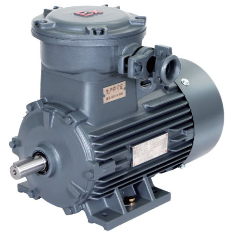
1MT0003 series flameproof motors
Classification of zones
Areas subject to explosion hazard are divided into zones. Zoning is based on the presence time of explosive substances and probability of explosion. Information and specifications for classification of the zones are laid down in the following standards:
GB 3836.14, IEC/EN 60079-10-1 for gas atmospheres
GB 12476.3, IEC/EN 60079-10-2 for dust atmospheres
Furthermore, a distinction is made between various explosion groups as well as temperature classes and these are included in the hazard assessment.
Depending on the particular zone and therefore the associated hazard, operating equipment must comply with defined minimum requirements regarding the type of protection. The different types of protection require corresponding measures to prevent ignition that should be implemented at the motor in order to prevent a surrounding explosive atmosphere from being ignited.
| Zone | Zone definition acc. toGB3836.14 & IEC/EN 60079-10-1 for gas atmospheres GB 12476.3 & IEC/EN 60079-10-2 for dust atmospheres | Assigned types of protection | Category according to 2014/34/EU | Equipment protection level acc. to GB3836.1 & IEC/EN 60079-0 | |
|---|---|---|---|---|---|
| Gas | Dust | ||||
| 0 | – | An area in which there is an explosive gas atmosphere constantly, over a long period or frequently. | Low-voltage motors not permitted | 1 | Ga |
| 1 | – | An area in which it is expected that an explosive gas atmosphere will occur occasionally during normal operation. | Ex e(GB) or Ex eb(IEC), Ex de, Ex d(GB) or Ex db(IEC) | 2 | Gb |
| 2 | – | An area in which it is expected that an explosive gas atmosphere will occur only rarely and then only briefly during normal operation. | Ex nA(GB) or Ex ec(IEC) | 3 | Gc |
| – | 20 | An area in which there is an explosive gas atmosphere comprising a dust-air mixture constantly, over a long period or frequently. | Low-voltage motors not permitted | 1 | Da |
| – | 21 | An area in which it is expected that an explosive gas atmosphere comprising a dust-air mixture will occur occasionally during normal operation. | Ex tb | 2 | Db |
| – | 22 | An area in which it is expected that an explosive gas atmosphere in the form of a cloud of flammable dust in air will occur only rarely and then only briefly during normal operation. | Ex tc 3) | 3 | Dc |
Application
The explosion-proof motors are often used in the following industries to prevent explosion hazards that result in serious injury to persons and severe damage to property.
Chemical and petrochemical industry,Production of mineral oil and gas,Gas works,Gas supply companies,Petrol stations,Coking plants,Mills (e.g. corn, solids),Sewage treatment plants,Wood processing (e.g. sawdust, tree resin),Other industries subject to explosion hazards.
Flameproof class of gases and vapors
| Location | Code of standardGB3836.1 / GB3836.2 / IEC60079-0 / IEC60079-1Flameproof class |
|---|---|
| For Mines | d Ⅰ |
| Explosive gas environment except mines | d Ⅱ A |
| d Ⅱ B | |
| d Ⅱ C |
Temperature classes(ºC )
| Temperature class of electrical equipment | lMaximum surface temperature of electrical equipment | Ignition temperature of gases or vapors |
|---|---|---|
| T1 | 450ºC | > 450ºC |
| T2 | 300ºC | > 300ºC |
| T3 | 200ºC | > 200ºC |
| T4 | 135ºC | > 135ºC |
| T5 | 100ºC | > 100ºC |
| T6 | 85ºC | > 85ºC |
Classification of gases and vapors into explosion groups and temperature classes
| explosion group | Temperatureclasses(ºC) | |||||
|---|---|---|---|---|---|---|
| T1(450) | T2(300) | T3(200) | T4(135) | T5(100) | T6(85) | |
| Material designation | Material designation | Material designation | Material designation | Material designation | Material designation | |
| IIA (MESG≥0.9mm) | Acetone | i-amyl acetate | Benzine | Acetaldehyde | ||
| Ethane | n-butane | Gasoline | ||||
| Ethyl acetate | n-butyl alcohol | Special benzine | ||||
| Ethyl chloride | Cyclohexanone | Diesel fuel | ||||
| Ammonia | 1.2- dichloroethane | Heating oils | ||||
| Benzene | Acetic acid anhydride | n-hexane | ||||
| Acetic acid | ||||||
| Carbon monoxide | ||||||
| Methane | ||||||
| Methanol | ||||||
| Methyl chloride | ||||||
| Naphthalene | ||||||
| Phenol | ||||||
| Propane | ||||||
| Toluene | ||||||
| IIB (0.5mm<MESG<0.9mm) | Town gas (illuminating gas) | Ethyl alcohol | Hydrogen sulfide | Ethyl ether | ||
| Ethylene | ||||||
| Ethylene oxide | ||||||
| IIC (MESG≤0.5mm) | Hydrogen | Acetylene | Carbon disulfide | |||
MESG, maximum experimental safe gap (for an explosive mixture). It's maximum gap of a joint of 25 mm in width which prevents any transmission of anexplosion during 10 test smade under the conditions specified in GB 3836.11 and IEC60079-20-1.
The smaller the MESG value, the higher the explosion-proof level of the equipment, and the more stringent requirements for the equipment. If the equipment can run under the IIC gas group, it also meets the requirements of IIA and IIB.
Product overview
- Rated output:0.55 ~ 315kW
- Frame size:80 ~355
- Voltage and Frequency:380V 50Hz 380/660V50Hz ,Other common voltage canbe provide as option design
- Standardcolor:RAL7011
- Coolingmethod:IC411
- Frame-proof marking:Ex d IIB T4Gb
- Protectdegree:IP55
- Insulationclass:F
- Re-greasing device:FS 280 ~ 355 motoras standard,FS160~250motorasoptiondesign
- Ambient temperature:-20ºC ~ 40ºC asstandard
1MT0003 series flameproof motors is newly designed totally enclosed fan cooling (TEFC) high efficiency motor. This series flameproof motor completely meet the standard of IEC 60079- 0:2017/IEC 60079-1:2017 and GB 3836.1-2010/GB 3836.2-2010. The type of
protection for this motor is Ex d IIB T4 Gb. And its efficiency fulfill efficiency grade IE3 (50Hz) of IEC 60034-30, and also Grade 2 efficiency of GB 18613-2012.
This series products have excellent performance, safe and reliable to use, simple and flexible installation, easy to maintain, low vibration, low noise.
1MT0003 series high-efficiency flameproof motors can be widely used in petroleum, chemical industry, oil and gas and other hazardous areas and places.These motors are designed such that an explosion within the housing cannot result in an explosion in the environment. The energy that is generated internally by an explosion is dissipated in the so-called “flameproof enclosure” so far that the energy is no longer sufficient for ignition outside the casing.
Noise levels
The noise levels are measured in accordance with DIN EN ISO 1680 in a anechoic room. It is specified as the A-valued measuring-surface sound pressure level Lpfa in dB (A). This is the spatial mean value of the sound pressure levels measured on the measuring surface. The measuring surface is a cube 1 m away from the motor surface. The sound power level is also specified as LWA in dB (A). Please find the noise value in technical data table, the specified values are only valid for totally enclosed fan cooling (cooling method: IC411) motor with no load at 50 Hz with no load, and the tolerance is +3 dB. While motor operating 60 Hz with no load, the values are approximately +4 dB (A) higher.
Vibration
1MT0003 rotors are dynamically balanced to severity grade A using a half key. Table below contains the effective vibration values for unloaded motors. Vibration grade B can be provided as option.
| Vibration grade | Mounting type | 56 ≤ FS ≤ 132 | 160 ≤ FS ≤ 280 | 280 < FS ≤ 355 | |||
|---|---|---|---|---|---|---|---|
| Vibration velocity (mm/s) | Vibration acceleration (mm/s2) | Vibration velocity (mm/s) | Vibration acceleration (mm/s2) | Vibration velocity (mm/s) | Vibration acceleration(mm/s2) | ||
| A | Free suspension | 1.6 | 2.5 | 2.2 | 3.5 | 2.8 | 4.4 |
| Rigid mounting | 1.3 | 2.0 | 1.8 | 2.8 | 2.3 | 3.6 | |
| B | Free suspension | 0.7 | 1.1 | 1.1 | 1.7 | 1.8 | 2.8 |
| Rigid mounting | - | - | 0.9 | 1.4 | 1.5 | 2.4 | |
Nameplate example

Ex-Mark
Construction and mounting type
| Construction type | With feet and without flange on the end-shield (DE) | |||||||||
|---|---|---|---|---|---|---|---|---|---|---|
| Mounting type | IM B3 FS 80~355 | IM B6 FS 80~160 | IM B7③ FS80~160 |
IM B8④ FS80~160 |
IM V5 ① FS80~160 |
IM V6 ② FS 80~160 |
||||
| Diagram |  |
 |
 |
 |
 |
 |
||||
| Letter, position 14th of Motor code | A | T | U | V | C | D | ||||
| Construction type | Without feet and with flange on the end-shield (DE) | With feet and with flange on the end-shield (DE) | ||||||||
| Mounting type | IM B5 FS 80~280 | IM V1 ①FS 80~355 | IM V3 ②FS80~160 | IM B35 FS80~355 | IMV15 ①FS80~160 | |||||
| Diagram |  |
 |
 |
 |
 |
|||||
| Letter, position 14th of Motor code | F | G | H | J | W | |||||
| Construction type | Without feet and with C-flange on driven end-shield (DE) | With feet and with C-flange on driven end-shield (DE) | ||||||||
| Mounting type | IM B14 FS 80 ~ 160 | IM V18 ①FS 80 ~ 160 | IM V19 ②FS 80 ~ 160 | IM B34 FS 80 ~ 160 | ||||||
| Diagram |  |
 |
 |
 |
||||||
| Letter, position 14th of Motor code | K | M | L | N | ||||||
Bearing Assignment
1MT0003 series motor are supplied with ball bearing as standard, these bearings are either sealed or regreasable type. Bearing design meets
the requirements of explosion protection. Fixed bearing at NDE is as standard configuration for FS160 ~3 55 motors;For FS80 ~ 132 motors the bearings are floating, fixed bearing at DE can be ordered with option code L20.
If higher cantilever force on the shaft required, the increased cantilever bearing design (Option code: L22) should be considered.
Asstandard,FS80~250 motors are not with regreasing device, but re-greasing device (Option code: L23) can be configured in FS160~250. FS280 ~ 355 motors with regreasable bearing and regreasing device is configured asstandard.
The following table lists the standard bearing configuration.
| Frame size | Number of poles | Standard design | Optional design | ||
|---|---|---|---|---|---|
| Horizontal / Vertical mounting | Increased cantilever force (option code L22) | ||||
| DEbearing | NDEbearing | DEbearing | NDEbearing | ||
| 80 | 2 ~ 6 | 6204-2RZ C3 | 6204-2RZ C3 | - | - |
| 90 | 2 ~ 6 | 6205-2RZ C3 | 6205-2RZ C3 | - | - |
| 100 | 2 ~ 6 | 6306-2RZ C3 | 6306-2RZ C3 | - | - |
| 112 | 2 ~ 6 | 6306-2RZ C3 | 6306-2RZ C3 | - | - |
| 132 | 2 ~ 8 | 6308-2RZ C3 | 6308-2RZ C3 | - | - |
| 160 | 2 ~ 8 | 6309-2RZ C3 | 6309-2RZ C3 | NU309 | 6309 C3 |
| 180 | 2 ~ 8 | 6310-2RZ C3 | 6310-2RZ C3 | NU310 | 6310 C3 |
| 200 | 2 ~ 8 | 6312 C3 | 6312 C3 | NU312 | 6312 C3 |
| 225 | 2 ~ 8 | 6313 C3 | 6313 C3 | NU313 | 6313 C3 |
| 250 | 2 ~ 8 | 6315 C3 | 6315 C3 | NU315 | 6315 C3 |
| 280 | 2 | 6315 C3 | 6315 C3 | NU315 | 6315 C3 |
| 4 ~ 8 | 6317 C3 | 6317 C3 | NU317 | 6317 C3 | |
| 315 | 2 | 6316 C3 | 6316 C3 | NU316 | 6316 C3 |
| 4 ~ 8 | 6319 C3 | 6319 C3 | NU319 | 6319 C3 | |
| 355 | 2 | 6317 C3 | 6317 C3 | NU317 | 6317 C3 |
| 4~ 8 | 6320 C3 | 6320 C3 | NU320 | 6320 C3 | |
Grease life and re-greasing interval
对于不可再润滑的轴承,其润滑脂寿命与轴承寿命相当。
For permanent lubrication, the bearing grease lifetime is matched to the bearing lifetime.
润滑脂寿命和再润滑周期(电动机水平安装)Grease lifetime and re-greaseinterval (Horizontalinstallation)
| Using permanent lubrication bearing | ||
|---|---|---|
| Frame size | Poles | Grease lifetime up to CT 40oC ① |
| 80 ~ 250 | 2-8 | 20000 或(or)40000 ② |
| Frame size | Poles | Bearing | 标准环境温度下的润滑周期(小时)Interval under standard ambient temperature(h) |
|---|---|---|---|
| 160 | 2P | 6309 C3 NU309 | 4000 |
| 4~8P | 8000 | ||
| 180 | 2P | 6310 C3 NU310 | 4000 |
| 4~8P | 8000 | ||
| 200 | 2P | 6312 C3 NU312 | 4000 |
| 4~8P | 8000 | ||
| 225 | 2P | 6313 C3 NU313 | 4000 |
| 4~8P | 8000 | ||
| 250 | 2P | 6315 C3 NU315 | 4000 |
| 4~8P | 8000 | ||
| 280 | 2P | 6315 C3 NU315 | 4000 |
| 4P | 6317 C3 NU317 | 6000 | |
| 6~8P | 8000 | ||
| 315 | 2P | 6316 C3 NU316 | 3000 |
| 4P | 6319 C3 NU319 | 4000 | |
| 6~8P | 6000 | ||
| 355 | 2P | 6317 C3 NU317 | 3000 |
| 4P | 6320 C4 NU320 | 4000 | |
| 6~8P | 6000 |
When the motor runs outside of normal conditions, the bearing life will be reduced, such as the following conditions.
When motor runs beyond the rated speed, the increase of motor vibration will result in the extra radial and axial force on bearing. This will reduce the life ofbearing;
When the motor vibration increase due to the environment or other equipment, the bearing also will endure more radial and axial force. This also will reduce the life of bearing.
Connection boxes
The connection box is located on the top of motor housing as standard, and can be rotated by 4×90º to allow for cable entry from each direction. When selecting the entrance to the motor drive end, please notice whether there is enough space in front of the installation for the cable line. For the standard connection box with hoop gland, the motor of FS 80~225 has one hoop gland, and the motor of FS250~355 hastwo.
| FrameSize | No. of main terminal | Main terminal thread | No. of main cableentry | Hoop gland dia.(mm) | ②Cable diameter (mm) | ①Max. auxiliary terminal | ③Auxiliary cable entry |
|---|---|---|---|---|---|---|---|
| 80 | 3 | M5 | 1 | 1xΦ42 | 13~1419~2024~25 | 8 | 1xM16x1.5 /or 1xM20x1.5 |
| 90 | |||||||
| 100 | |||||||
| 112 | 6 | M5 | 8 | 1xM16x1.5 or 1xM20x1.5 /or 2xM16x1.5 /or 1xM16x1.5 + 1xM20x1.5 | |||
| 132 | |||||||
| 160 | 6 | M6 | 1 | 1xΦ58 | 13~1419~2025~2630~3134~35 | 20 | 1xM16x1.5 /or 1xM20x1.5 /or 1xM25x1.5 /or 2xM16x1.5 /or 1xM16x1.5+ 1xM20x1.51xM16x1.5 +1xM25x1.5 |
| 180 | |||||||
| 200 | 6 | M8 | 1 | 1xΦ72 | 19~2025~2631~3237~3841~42 | 20 | 1xM16x1.5 /or 1xM20x1.5 /or 1xM25x1.5 /or 2xM16x1.5 /or 1xM16x1.5+ 1xM20x1.51xM16x1.5 +1xM25x1.5 |
| 225 | |||||||
| 250 | 6 | M10 | 2 | 2xΦ72 | 19~2025~2631~3237~3841~42 | 20 | 1xM16x1.5 /or 1xM20x1.5 /or 1xM25x1.5 /or 2xM16x1.5 /or 1xM16x1.5+ 1xM20x1.51xM16x1.5 +1xM25x1.5 |
| 280 | |||||||
| 315 | 6 | M16 | 2 | 2xΦ90 | 30~3135~3644~4549~50 | 20 | 1xM16x1.5 /or 1xM20x1.5 /or 1xM25x1.5 /or 2xM16x1.5 /or 1xM16x1.5+ 1xM20x1.51xM16x1.5 +1xM25x1.5 |
| Frame Size | Size of Main Conduit entry |
|---|---|
| 80 | M30×2 |
| 90 | |
| 100 | |
| 112 | M30×2 |
| 132 | |
| 160 | M36×2 |
| 180 | |
| 200 | M48×2 |
| 225 | |
| 250 | M48×2 |
| 280 | |
| 315 | M64×2 |
| 355 |
Motor protection
Motors whose windings are at risk of condensation due to the climatic conditions, e.g. inactive motors in humid atmospheres or motors that are subjected to widely fluctuating temperatures can be equipped with anti-condensation heaters (Option code: Q04).
Anti-condensation heaters must be switched off during operation. When motor shut down, the heaters must be switched on.
The electrical parameters of anti-condensation heaters are shown in the following table.
| Frame size | Power (W) & voltage (V) |
|---|---|
| Q04 | |
| 80 ~ 90 | 20 W / 220 V |
| 100 ~ 112 | 30 W / 220 V |
| 132 ~ 160 | 40 W / 220 V |
| 180 ~ 200 | 50 W / 220 V |
| 225 ~ 280 | 60 W / 220 V |
| 315 | 80 W / 220 V |
| 355 | 100 W / 220 V |
Motor thermal overload protection
Motor thermal protection means to use of thermal protectors and thermal detectors incorporated into the stator windings or placed in other suitable positions in motor in order to protect them against serious damage due to thermaloverloads.
The order variants for motor protection are coded with letters in the 15th position of the Motor Order No., or ordered with Option code.
Electrical design
Rated Output
1MT0003 motors rated output powers means that the motor runs under continuous duty S1 (IEC 60034 - 1) operation when operated at ambient temperature from -20 ºC to 40 ºC and at altitudes of up to 1000 m over sea.
Voltage and Frequency
IEC 60034-1 differentiates between Category A (combination of voltage deviation ±5 % and frequency deviation ±2 %) and Category B (combination of voltage deviation ±10 % and frequency deviation +3 % / -5 %) for voltage and frequency fluctuations. The motors can supply their rated torque in both Category A and B. In Category A, the temperature rise is approximately 10 K higher than during normal operation.
| Standard 60034 - 1 | Category A | Category B |
|---|---|---|
| Voltage deviation | ±5 % | ±10 % |
| Frequency deviation | ±2 % | +3 % / -5 % |
| According to the standard, longer operation is not recommended for Category B. | ||
Tolerance for electrical data
- Efficiencyηat
Prated ≤ 150 kW: - 0.15 x (1 –η)
Prated> 150 kW: - 0.10 x (1 –η)
With η being a decimal number - Power factor - (1 – cosφ) / 6
Minimum absolute value: 0.02
Maximum absolute value: 0.07 - Slip ±20 % (for motors < 1 kW ±30 % is admissible)
- Locked-rotor current +20 %
- Locked-rotor torque -15 % to +25 %
- Breakdown torque -10 %
- Moment of inertia ±10 %
Overload times
According to IEC60034, 1MT0003 series motors are designed to withstand overload capacity of 1.5 times rated current for 2 minutes at rated voltage and frequency.
Order No. and Motor Type
 Foot note:Order other voltages with voltage code 90 and the corresponding Option code (see under "Option") .
Technical data table
| Frame Size | Order No. | Rated Output | Rated Speed | Effeciency is in accordance with GB18613-2012, IEC 60034-30 | Rated torque) | Starting Current | Starting torque | Max torque | Moment of inertia(J) | ①Noise LpfA | ① Noise LWA | Weight IMB3 | |||
|---|---|---|---|---|---|---|---|---|---|---|---|---|---|---|---|
| Effeciency at(50HZ)4/4 load | Effeciency at (50 HZ)3/4 load | Power factor | Rated current(380V | ||||||||||||
| KW | rpm | % | % | A | Nm | For direct-on-line starting as multiple of the rated | kgm² | dB(A) | dB(A) | kg | |||||
| 3000rpm 2 - pole | |||||||||||||||
| 380VY② 50HZ | |||||||||||||||
| 80M | 1MT0003-0DA29-0 ××× | 0.75 | 2835 | 80.7 | 82.9 | 0.86 | 1.64 | 2.5 | 6.0 | 2.4 | 3.0 | 0.0010 | 51 | 62 | 29 |
| 80M | 1MT0003-0DA39-0 ××× | 1.1 | 2870 | 82.7 | 84.0 | 0.83 | 2.45 | 3.7 | 6.5 | 2.4 | 3.4 | 0.0013 | 51 | 62 | 31 |
| 90S | 1MT0003-0EA09-0 ××× | 1.5 | 2900 | 84.2 | 84.8 | 0.86 | 3.15 | 4.9 | 6.5 | 2.0 | 3.4 | 0.0024 | 55 | 67 | 37 |
| 90L | 1MT0003-0EA49-0 ××× | 2.2 | 2910 | 85.9 | 87.2 | 0.88 | 4.4 | 7.2 | 7.5 | 2.3 | 3.6 | 0.0030 | 55 | 67 | 42 |
| 100L | 1MT0003-1AA49-0 ××× | 3 | 2875 | 87.1 | 88.3 | 0.87 | 6 | 10.0 | 7.8 | 2.6 | 3.6 | 0.0046 | 62 | 74 | 54 |
| 3000rpm 2 - pole | |||||||||||||||
| 380VD/660VY 50HZ | |||||||||||||||
| 112M | 1MT0003-1BA23-3 ××× | 4 | 2925 | 88.1 | 89.6 | 0.90 | 7.7 | 13.1 | 7.8 | 2.6 | 3.6 | 0.0087 | 65 | 77 | 67 |
| 132S | 1MT0003-1CA03-3 ××× | 5.5 | 2930 | 89.2 | 90.2 | 0.89 | 10.5 | 17.9 | 7.5 | 2.3 | 3.6 | 0.018 | 67 | 79 | 84 |
| 132S | 1MT0003-1CA13-3 ××× | 7.5 | 2925 | 90.1 | 91.5 | 0.90 | 14.1 | 24.5 | 7.5 | 2.3 | 3.6 | 0.022 | 67 | 79 | 92 |
| 160M | 1MT0003-1DA23-3 ××× | 11 | 2935 | 91.2 | 92.0 | 0.89 | 20.5 | 35.8 | 7.5 | 2.3 | 2.5 | 0.037 | 69 | 81 | 140 |
| 160M | 1MT0003-1DA33-3 ××× | 15 | 2930 | 91.9 | 92.6 | 0.89 | 28 | 48.9 | 7.5 | 2.4 | 3.4 | 0.045 | 69 | 81 | 150 |
| 160L | 1MT0003-1DA43-3 ××× | 18.5 | 2940 | 92.4 | 93.0 | 0.89 | 34 | 60.1 | 7.8 | 2.4 | 3.4 | 0.054 | 69 | 81 | 170 |
| 180M | 1MT0003-1EA23-3 ××× | 22 | 2950 | 92.7 | 93.0 | 0.89 | 40.5 | 71.2 | 7.8 | 2.4 | 3.4 | 0.088 | 70 | 83 | 207 |
| 200L | 1MT0003-2AA43-3 ××× | 30 | 2955 | 93.3 | 93.4 | 0.87 | 56 | 97.0 | 7.8 | 2.4 | 3.4 | 0.156 | 71 | 84 | 290 |
| 200L | 1MT0003-2AA53-3 ××× | 37 | 2955 | 93.7 | 93.9 | 0.89 | 67 | 120 | 7.8 | 2.4 | 3.4 | 0.183 | 71 | 84 | 321 |
| 225M | 1MT0003-2BA23-3 ××× | 45 | 2960 | 94.0 | 94.3 | 0.89 | 82 | 145 | 7.8 | 2.4 | 3.2 | 0.301 | 72 | 85 | 401 |
| 250M | 1MT0003-2CA23-3 ××× | 55 | 2975 | 94.3 | 94.1 | 0.89 | 100 | 177 | 7.8 | 2.4 | 3.2 | 0.507 | 75 | 89 | 483 |
| 280S | 1MT0003-2DA03-3 ××× | 75 | 2975 | 94.7 | 94.8 | 0.89 | 135 | 241 | 7.2 | 2.4 | 3.0 | 0.856 | 77 | 91 | 600 |
| 280M | 1MT0003-2DA23-3 ××× | 90 | 2975 | 95.0 | 95.3 | 0.90 | 160 | 289 | 7.2 | 2.4 | 3.4 | 1.029 | 77 | 91 | 665 |
| 315S | 1MT0003-3AA03-3 ××× | 110 | 2975 | 95.2 | 95.1 | 0.90 | 195 | 353 | 7.9 | 1.8 | 2.6 | 1.75 | 78 | 92 | 980 |
| 315M | 1MT0003-3AA23-3 ××× | 132 | 2980 | 95.4 | 95.3 | 0.90 | 235 | 423 | 7.9 | 2.1 | 2.6 | 1.77 | 78 | 92 | 1030 |
| 315L | 1MT0003-3AA53-3 ××× | 160 | 2978 | 95.6 | 95.7 | 0.91 | 280 | 513 | 7.9 | 2.1 | 2.6 | 2.10 | 78 | 92 | 1130 |
| 315L | 1MT0003-3AA63-3 ××× | 185 | 2978 | 95.7 | 95.9 | 0.92 | 320 | 593 | 7.9 | 2.3 | 2.6 | 2.52 | 78 | 92 | 1210 |
| 315L | 1MT0003-3AA73-3 ××× | 200 | 2982 | 95.8 | 95.9 | 0.92 | 345 | 641 | 7.9 | 2.6 | 3.2 | 2.52 | 78 | 92 | 1230 |
| 355M | 1MT0003-3BA23-3 ××× | 220 | 2986 | 95.8 | 95.4 | 0.90 | 390 | 704 | 8.5 | 2.2 | 2.8 | 2.65 | 85 | 100 | 1600 |
| 355M | 1MT0003-3BA33-3 ××× | 250 | 2985 | 95.8 | 95.7 | 0.90 | 440 | 800 | 8.0 | 2.2 | 2.8 | 2.65 | 85 | 100 | 1600 |
| 355L | 1MT0003-3BA53-3 ××× | 280 | 2988 | 95.8 | 95.7 | 0.90 | 495 | 896 | 8.5 | 2.2 | 2.8 | 3.24 | 85 | 100 | 1730 |
| 355L | 1MT0003-3BA63-3 ××× | 315 | 2982 | 95.8 | 95.8 | 0.90 | 560 | 1009 | 8.0 | 2.2 | 2.8 | 3.24 | 85 | 100 | 1780 |
| Frame Size | Order No. | Rated Output | Rated Speed | Effeciency is in accordance with GB18613-2012, IEC 60034-30 | Rated torque) | Starting Current | Starting torque | Max torque | Moment of inertia(J) | ① Noise LpfA | ① Noise LWA | Weight IMB3 | |||
|---|---|---|---|---|---|---|---|---|---|---|---|---|---|---|---|
| Effeciency at(50HZ)4/4 load | Effeciency at (50 HZ)3/4 load | Power factor | Rated current(380V | ||||||||||||
| KW | rpm | % | % | A | Nm | For direct-on-line starting as multiple of the rated | kgm² | dB(A) | dB(A) | kg | |||||
| 1500rpm 4 - pole | |||||||||||||||
| 380VY② 50HZ | |||||||||||||||
| 80M | 1MT0003-0DB29-0 ××× | 0.55 | 1440 | 80.8 | 81.8 | 0.76 | 1.36 | 3.6 | 5.5 | 2.2 | 3.2 | 0.0021 | 45 | 56 | 30 |
| 80M | 1MT0003-0DB39-0 ××× | 0.75 | 1445 | 82.5 | 82.9 | 0.75 | 1.84 | 5.0 | 6.0 | 2.7 | 3.7 | 0.0024 | 45 | 56 | 31 |
| 90S | 1MT0003-0EB09-0 ××× | 1.1 | 1430 | 84.1 | 85.1 | 0.79 | 2.5 | 7.3 | 6.5 | 2.7 | 3.7 | 0.0039 | 47 | 59 | 37 |
| 90L | 1MT0003-0EB49-0 ××× | 1.5 | 1440 | 85.3 | 86.0 | 0.79 | 3.4 | 9.9 | 6.5 | 2.7 | 3.8 | 0.0050 | 47 | 59 | 42 |
| 100L | 1MT0003-1AB49-0 ××× | 2.2 | 1445 | 86.7 | 87.1 | 0.82 | 4.7 | 14.5 | 8.3 | 3.7 | 4.6 | 0.0112 | 52 | 64 | 57 |
| 100L | 1MT0003-1AB59-0 ××× | 3 | 1450 | 87.7 | 88.1 | 0.82 | 6.3 | 19.8 | 8.3 | 3.7 | 4.6 | 0.0132 | 52 | 64 | 61 |
| 1500rpm 4 - pole | |||||||||||||||
| 380VD/660VY 50HZ | |||||||||||||||
| 112M | 1MT0003-1BB23-3 ××× | 4 | 1450 | 88.6 | 89.6 | 0.82 | 8.4 | 26.3 | 8.3 | 3.7 | 4.6 | 0.0148 | 53 | 65 | 72 |
| 132S | 1MT0003-1CB03-3 ××× | 5.5 | 1455 | 89.6 | 90.9 | 0.84 | 11.1 | 36.1 | 7.8 | 2.4 | 3.8 | 0.028 | 59 | 71 | 91 |
| 132M | 1MT0003-1CB23-3 ××× | 7.5 | 1455 | 90.4 | 91.7 | 0.85 | 14.8 | 49.2 | 7.8 | 2.4 | 3.8 | 0.035 | 59 | 71 | 105 |
| 160M | 1MT0003-1DB23-3 ××× | 11 | 1460 | 91.4 | 92.4 | 0.86 | 21.5 | 72.0 | 7.8 | 2.4 | 3.8 | 0.063 | 61 | 73 | 150 |
| 160L | 1MT0003-1DB43-3 ××× | 15 | 1460 | 92.1 | 92.9 | 0.86 | 29 | 98.1 | 7.8 | 2.6 | 3.8 | 0.078 | 61 | 73 | 173 |
| 180M | 1MT0003-1EB23-3 ××× | 18.5 | 1470 | 92.6 | 93.0 | 0.83 | 36.5 | 120 | 7.8 | 2.6 | 3.6 | 0.134 | 63 | 76 | 208 |
| 180L | 1MT0003-1EB43-3 ××× | 22 | 1470 | 93.0 | 93.7 | 0.83 | 43.5 | 143 | 7.8 | 2.6 | 3.6 | 0.153 | 63 | 76 | 228 |
| 200L | 1MT0003-2AB43-3 ××× | 30 | 1470 | 93.6 | 94.3 | 0.84 | 58 | 195 | 7.8 | 2.6 | 3.6 | 0.247 | 63 | 76 | 302 |
| 225S | 1MT0003-2BB03-3 ××× | 37 | 1478 | 93.9 | 94.1 | 0.83 | 72 | 239 | 8.3 | 3.3 | 3.6 | 0.495 | 65 | 78 | 366 |
| 225M | 1MT0003-2BB23-3 ××× | 45 | 1478 | 94.2 | 94.2 | 0.85 | 85 | 291 | 8.3 | 3.3 | 3.6 | 0.549 | 65 | 78 | 402 |
| 250M | 1MT0003-2CB23-3 ××× | 55 | 1482 | 94.6 | 95.0 | 0.86 | 103 | 354 | 7.6 | 2.6 | 3.3 | 0.892 | 66 | 79 | 500 |
| 280S | 1MT0003-2DB03-3 ××× | 75 | 1485 | 95.0 | 95.3 | 0.86 | 139 | 482 | 7.6 | 2.6 | 3.0 | 1.463 | 66 | 80 | 635 |
| 280M | 1MT0003-2DB23-3 ××× | 90 | 1485 | 95.2 | 95.6 | 0.87 | 165 | 579 | 7.6 | 2.6 | 3.0 | 1.862 | 66 | 80 | 740 |
| 315S | 1MT0003-3AB03-3 ××× | 110 | 1488 | 95.4 | 95.7 | 0.87 | 200 | 706 | 7.9 | 3.3 | 3.0 | 2.32 | 74 | 88 | 990 |
| 315M | 1MT0003-3AB23-3 ××× | 132 | 1488 | 95.6 | 95.9 | 0.87 | 240 | 847 | 7.9 | 3.3 | 3.0 | 3.17 | 74 | 88 | 1140 |
| 315L | 1MT0003-3AB53-3 ××× | 160 | 1488 | 95.8 | 96.1 | 0.87 | 290 | 1027 | 7.9 | 3.3 | 3.0 | 3.31 | 74 | 88 | 1170 |
| 315L | 1MT0003-3AB63-3 ××× | 185 | 1488 | 95.9 | 96.2 | 0.87 | 335 | 1187 | 7.9 | 3.3 | 3.0 | 3.66 | 74 | 88 | 1220 |
| 315L | 1MT0003-3AB73-3 ××× | 200 | 1490 | 96.0 | 96.3 | 0.88 | 360 | 1282 | 7.9 | 3.3 | 3.0 | 4.00 | 74 | 88 | 1280 |
| 355M | 1MT0003-3BB23-3 ××× | 220 | 1492 | 96.0 | 96.0 | 0.88 | 395 | 1408 | 8.0 | 2.0 | 3.2 | 5.20 | 81 | 95 | 1780 |
| 355M | 1MT0003-3BB33-3 ××× | 250 | 1490 | 96.0 | 96.0 | 0.88 | 450 | 1602 | 7.8 | 1.8 | 2.9 | 5.20 | 81 | 95 | 1780 |
| 355L | 1MT0003-3BB53-3 ××× | 280 | 1490 | 96.0 | 96.1 | 0.88 | 500 | 1795 | 7.8 | 1.8 | 2.9 | 5.50 | 81 | 95 | 1810 |
| 355L | 1MT0003-3BB63-3 ××× | 315 | 1490 | 96.0 | 96.1 | 0.88 | 570 | 2019 | 8.0 | 1.8 | 2.9 | 5.95 | 81 | 95 | 1930 |
| Frame Size | Order No. | Rated Output | Rated Speed | Effeciency is in accordance with GB18613-2012, IEC 60034-30 | Rated torque) | Starting Current | Starting torque | Max torque | Moment of inertia(J) | ① Noise LpfA | ① Noise LWA | Weight IMB3 | |||
|---|---|---|---|---|---|---|---|---|---|---|---|---|---|---|---|
| Effeciency at(50HZ)4/4 load | Effeciency at (50 HZ)3/4 load | Power factor | Rated current(380V | ||||||||||||
| KW | rpm | % | % | A | Nm | For direct-on-line starting as multiple of the rated | kgm² | dB(A) | dB(A) | kg | |||||
| 1000rpm 6 - pole | |||||||||||||||
| 380VY② 50HZ | |||||||||||||||
| 80M | 1MT0003-0DC39-0 ××× | 0.55 | 935 | 77.2 | 77.5 | 0.67 | 1.62 | 5.6 | 5.0 | 2.7 | 3.4 | 0.0030 | 44 | 55 | 33 |
| 90S | 1MT0003-0EC09-0 ××× | 0.75 | 940 | 78.9 | 80.3 | 0.70 | 2.05 | 7.6 | 5.0 | 2.4 | 3.2 | 0.0042 | 45 | 57 | 39 |
| 90L | 1MT0003-0EC49-0 ××× | 1.1 | 945 | 81.0 | 81.6 | 0.69 | 3 | 11.1 | 5.5 | 2.7 | 3.5 | 0.0050 | 45 | 57 | 42 |
| 100L | 1MT0003-1AC49-0 ××× | 1.5 | 945 | 82.5 | 84.1 | 0.74 | 3.75 | 15.2 | 5.5 | 2.7 | 3.5 | 0.0113 | 49 | 61 | 58 |
| 112M | 1MT0003-1BC29-0 ××× | 2.2 | 945 | 84.3 | 86.1 | 0.74 | 5.4 | 22.2 | 6.0 | 2.7 | 3.4 | 0.0136 | 53 | 65 | 70 |
| 132S | 1MT0003-1CC09-0 ××× | 3 | 965 | 85.6 | 86.6 | 0.75 | 7.1 | 29.7 | 6.0 | 2.7 | 4.0 | 0.026 | 57 | 69 | 87 |
| 1000rpm 6 - pole | |||||||||||||||
| 380VD/660VY 50HZ | |||||||||||||||
| 132M | 1MT0003-1CC23-3 ××× | 4 | 955 | 86.8 | 88.5 | 0.75 | 9.3 | 40.0 | 6.0 | 2.3 | 3.4 | 0.030 | 57 | 69 | 97 |
| 132M | 1MT0003-1CC33-3 ××× | 5.5 | 960 | 88.0 | 89.2 | 0.76 | 12.5 | 54.7 | 6.5 | 2.3 | 4.0 | 0.040 | 57 | 69 | 111 |
| 160M | 1MT0003-1DC23-3 ××× | 7.5 | 965 | 89.1 | 90.4 | 0.78 | 16.4 | 74.2 | 6.5 | 2.3 | 3.6 | 0.119 | 61 | 73 | 149 |
| 160L | 1MT0003-1DC43-3 ××× | 11 | 970 | 90.3 | 90.3 | 0.77 | 24 | 108 | 7.0 | 2.3 | 3.6 | 0.169 | 61 | 73 | 180 |
| 180L | 1MT0003-1EC43-3 ××× | 15 | 975 | 91.2 | 92.1 | 0.80 | 31 | 147 | 7.0 | 2.3 | 3.0 | 0.206 | 59 | 73 | 212 |
| 200L | 1MT0003-2AC43-3 ××× | 18.5 | 978 | 91.7 | 92.5 | 0.80 | 38.5 | 181 | 7.0 | 2.3 | 3.0 | 0.312 | 59 | 73 | 284 |
| 200L | 1MT0003-2AC53-3 ××× | 22 | 978 | 92.2 | 93.1 | 0.80 | 45.5 | 215 | 7.0 | 2.4 | 3.0 | 0.357 | 59 | 73 | 299 |
| 225M | 1MT0003-2BC23-3 ××× | 30 | 982 | 92.9 | 93.9 | 0.83 | 59 | 292 | 7.6 | 2.4 | 3.0 | 0.761 | 60 | 74 | 410 |
| 250M | 1MT0003-2CC23-3 ××× | 37 | 985 | 93.3 | 94.1 | 0.84 | 72 | 359 | 7.6 | 2.4 | 3.0 | 1.070 | 62 | 76 | 487 |
| 280S | 1MT0003-2DC03-3 ××× | 45 | 985 | 93.7 | 94.5 | 0.84 | 87 | 436 | 7.8 | 3.0 | 3.0 | 1.484 | 64 | 78 | 580 |
| 280M | 1MT0003-2DC23-3 ××× | 55 | 988 | 94.1 | 94.6 | 0.84 | 106 | 532 | 7.8 | 3.0 | 3.0 | 1.748 | 64 | 78 | 645 |
| 315S | 1MT0003-3AC03-3 ××× | 75 | 990 | 94.6 | 95.0 | 0.84 | 143 | 723 | 7.8 | 2.6 | 3.0 | 2.92 | 69 | 83 | 980 |
| 315M | 1MT0003-3AC23-3 ××× | 90 | 990 | 94.9 | 95.3 | 0.84 | 172 | 868 | 7.8 | 2.6 | 3.0 | 3.47 | 69 | 83 | 1060 |
| 315L | 1MT0003-3AC53-3 ××× | 110 | 991 | 95.1 | 95.3 | 0.85 | 205 | 1060 | 7.8 | 2.6 | 3.0 | 4.43 | 69 | 83 | 1180 |
| 315L | 1MT0003-3AC63-3 ××× | 132 | 991 | 95.4 | 95.7 | 0.85 | 245 | 1272 | 7.8 | 2.6 | 3.0 | 4.75 | 69 | 83 | 1230 |
| 355S | 1MT0003-3BC23-3 ××× | 160 | 994 | 95.6 | 95.7 | 0.84 | 305 | 1537 | 8.5 | 3.0 | 2.4 | 10.57 | 71 | 85 | 1800 |
| 355M | 1MT0003-3BC33-3 ××× | 185 | 993 | 95.7 | 95.8 | 0.84 | 350 | 1779 | 8.5 | 3.0 | 2.4 | 10.60 | 71 | 85 | 1870 |
| 355M | 1MT0003-3BC43-3 ××× | 200 | 993 | 95.8 | 95.9 | 0.84 | 380 | 1923 | 8.5 | 3.0 | 2.4 | 11.09 | 71 | 85 | 1910 |
| 355L | 1MT0003-3BC53-3 ××× | 220 | 993 | 95.8 | 96.0 | 0.84 | 415 | 2116 | 8.5 | 3.0 | 2.4 | 13.09 | 71 | 85 | 2080 |
| 355L | 1MT0003-3BC63-3 ××× | 250 | 992 | 95.8 | 96.1 | 0.84 | 470 | 2407 | 8.5 | 3.0 | 2.4 | 13.09 | 71 | 85 | 2110 |
| Frame Size | Order No. | Rated Output | Rated Speed | Effeciency is in accordance with IEC 60034-30 | Rated torque) | Starting Current | Starting torque | Max torque | Moment of inertia(J) | ① Noise LpfA | ① Noise LWA | Weight IMB3 | |||
|---|---|---|---|---|---|---|---|---|---|---|---|---|---|---|---|
| Effeciency at(50HZ)4/4 load | Effeciency at (50 HZ)3/4 load | Power factor | Rated current(380V | ||||||||||||
| KW | rpm | % | % | A | Nm | For direct-on-line starting as multiple of the rated | kgm² | dB(A) | dB(A) | kg | |||||
| 750rpm 8-pole | |||||||||||||||
| 380VY② 50HZ | |||||||||||||||
| 132S | 1MT0003-1CD09-0 ××× | 2.2 | 725 | 81.9 | 82.6 | 0.73 | 5.6 | 29.0 | 6.0 | 2.4 | 3.0 | 0.047 | 51 | 64 | 83 |
| 132M | 1MT0003-1CD29-0 ××× | 3 | 725 | 83.5 | 84.5 | 0.74 | 7.4 | 39.5 | 6.0 | 2.4 | 3.0 | 0.062 | 51 | 64 | 97 |
| 750rpm 8-pole | |||||||||||||||
| 380VD/660VY 50HZ | |||||||||||||||
| 160M | 1MT0003-1DD23-3 ××× | 4 | 728 | 84.8 | 86.4 | 0.74 | 9.7 | 52.5 | 5.5 | 1.7 | 2.8 | 0.076 | 55 | 68 | 129 |
| 160M | 1MT0003-1DD33-3 ××× | 5.5 | 732 | 86.2 | 87.1 | 0.74 | 13.1 | 71.8 | 6.0 | 1.7 | 3.0 | 0.101 | 55 | 68 | 140 |
| 160L | 1MT0003-1DD43-3 ××× | 7.5 | 732 | 87.3 | 88.3 | 0.74 | 17.6 | 97.8 | 6.0 | 1.8 | 3.0 | 0.128 | 55 | 68 | 162 |
| 180L | 1MT0003-1ED43-3 ××× | 11 | 725 | 88.6 | 89.9 | 0.74 | 25.5 | 145 | 5.5 | 2.0 | 3.0 | 0.261 | 60 | 73 | 234 |
| 200L | 1MT0003-2AD53-3 ××× | 15 | 728 | 89.6 | 90.2 | 0.73 | 35 | 197 | 6.5 | 2.3 | 3.5 | 0.413 | 61 | 74 | 313 |
| 225S | 1MT0003-2BD03-3 ××× | 18.5 | 735 | 90.1 | 90.9 | 0.75 | 41.5 | 240 | 5.9 | 2.0 | 3.0 | 0.552 | 58 | 72 | 331 |
| 225M | 1MT0003-2BD23-3 ××× | 22 | 732 | 90.6 | 91.5 | 0.75 | 49 | 287 | 5.9 | 2.0 | 2.5 | 0.608 | 58 | 72 | 358 |
| 250M | 1MT0003-2CD23-3 ××× | 30 | 735 | 91.3 | 92.1 | 0.79 | 63 | 390 | 6.5 | 2.0 | 3.0 | 0.924 | 67 | 80 | 450 |
| 280S | 1MT0003-2DD03-3 ××× | 37 | 736 | 91.8 | 92.8 | 0.79 | 78 | 480 | 5.5 | 1.7 | 2.5 | 1.183 | 69 | 82 | 540 |
| 280M | 1MT0003-2DD23-3 ××× | 45 | 738 | 92.2 | 93.1 | 0.80 | 93 | 582 | 6.0 | 1.8 | 2.5 | 1.736 | 69 | 82 | 650 |
| 315S | 1MT0003-3AD03-3 ××× | 55 | 739 | 92.5 | 93.0 | 0.81 | 112 | 710 | 6.2 | 2.0 | 2.9 | 2.16 | 70 | 83 | 860 |
| 315M | 1MT0003-3AD23-3 ××× | 75 | 738 | 93.1 | 93.6 | 0.81 | 151 | 970 | 6.7 | 2.2 | 2.5 | 2.70 | 70 | 83 | 955 |
| 315L | 1MT0003-3AD53-3 ××× | 90 | 738 | 93.4 | 93.9 | 0.82 | 179 | 1165 | 5.9 | 1.8 | 2.3 | 3.40 | 70 | 83 | 1000 |
| 315L | 1MT0003-3AD63-3 ××× | 110 | 741 | 93.7 | 94.2 | 0.82 | 220 | 1418 | 7.1 | 2.3 | 3.0 | 4.25 | 70 | 83 | 1150 |
| 355S | 1MT0003-3BD23-3 ××× | 132 | 743 | 94 | 94.5 | 0.81 | 265 | 1699 | 7.1 | 2.2 | 2.4 | 8.09 | 77 | 90 | 1630 |
| 355M | 1MT0003-3BD33-3 ××× | 160 | 742 | 94.3 | 94.8 | 0.81 | 320 | 2059 | 7.1 | 2.2 | 2.4 | 9.50 | 77 | 90 | 1840 |
| 355L | 1MT0003-3BD53-3 ××× | 185 | 742 | 94.6 | 95.0 | 0.82 | 360 | 2382 | 7.1 | 2.0 | 2.1 | 11.25 | 77 | 90 | 2010 |
| 355L | 1MT0003-3BD63-3 ××× | 200 | 742 | 94.6 | 95.0 | 0.83 | 385 | 2576 | 7.4 | 2.0 | 2.1 | 12.63 | 77 | 90 | 2120 |
Options
| Motor order code | Option Code ① | Description | Application Scope |
|---|---|---|---|
| Voltages and frequency | |||
| 1MT0003-××××2-1××× | - | 220VΔ / 380VY 50 Hz(50Hz output) | FS112 ~ 2803) |
| 1MT0003-××××3-3××× | - | 380VΔ / 660VY 50 Hz(50Hz output,4 kW ~ 315 kW 2)) | FS112 ~ 3553) |
| 1MT0003-××××2-2××× | - | 230VΔ / 400VY 50 Hz(50Hz output, ) | FS112 ~ 2803) |
| 1MT0003-××××3-4××× | - | 400VΔ / 690VY 50 Hz(50Hz output, ) | FS112 ~ 3553) |
| 1MT0003-××××9-0×××-Z | M3F ② | 380 VY 50 Hz(50Hz output) | FS80 ~ 132④ |
| Winding protection and bearing protection | |||
| 1MT0003-×××××-××A×② | - | Without motor protection | FS80 ~ 355 |
| 1MT0003-×××××-××B× | - | Motor protection with PTC thermistors with three embedded temperature sensors for tripping, need 2 terminals | FS80 ~ 355 |
| 1MT0003-×××××-××C× | - | Motor protection with PTC thermistors with six embedded temperature sensors for alarm & tripping, need 4 terminals | FS80 ~ 355 |
| 1MT0003-×××××-××H×-Z | - | Installation of 3 single 2 wires PT100 resistance thermometers, need 6 terminals | FS100 ~ 355 |
| 1MT0003-×××××-××J×-Z | - | Installation of 6 single 2 wires PT100 resistance thermometers, need 12 terminals | FS180 ~ 355 |
| - | Q04 | Anti-condensation heating for 220 V | FS80 ~ 355 |
| - | Q72 ⑤ | Installation of 2 single 2 wires PT100 resistance thermometers for bearings, need 4 terminals | FS160 ~ 355 |
| Ventilation | |||
| - | F76 | MetalFan | FS80 ~ 355 |
| Motor order code | Option Code ① | Description | Application Scope |
|---|---|---|---|
| Motor connection box | |||
| 1MT0003-×××××-×××4 ② | - | Connection box on top cable entry on right (view from DE) (Standard version) | FS80 ~ 355 |
| - | R10 ⑥ | Clockwise rotate the connection box through 90º | FS80 ~ 355 |
| - | R11 | Counter-clockwise rotate the connection box through 90º | FS80 ~ 355 |
| - | R12 | Rotation of the connection box through 180º | FS80 ~ 355 |
| - | X97 | Conduit entry | FS80 ~ 355 |
| bearing | |||
| - | L80 | SKF bearings | FS80 ~ 355 |
| - | L81 | Other import brand bearing | FS80 ~ 355 |
| - | L82 | DE shaft with threaded hole | FS80 ~ 355 |
| - | L20 | Located bearing at DE | FS80 ~ 132 |
| - | L22 | Bearing design for increased cantilever forces | FS160 ~ 355 |
| - | L23 ⑦ | Regreasing device | FS160 ~ 250 |
| Motor order code | Option Code ① | Description | Application Scope |
|---|---|---|---|
| Balance and Vibration quantity | |||
| - | L00 | Vibration quantity level B | FS80 ~ 355 |
| Mechanical design and degrees of protection | |||
| - | H70 | 2nd External grounding | FS80 ~ 355 |
| - | H22 | IP56 degree of protection (non-heavy-sea) | FS80 ~ 355 |
| Rating plate and test certificates | |||
| - | B80 | Acceptance test certificate 3.1 in accordance with EN 10204 | FS80 ~ 355 |
| Colors and Paint finish | |||
| - | S01 | Unpainted, only primed | FS80 ~ 355 |
| - | W88 ⑧ | Design for TH, W, F1, WF1 and sea-air resistance | FS80 ~ 355 |
| - | B90 | Packing(FS80~132 motors adopt the carton packaging, FS160~355 motors adopt the wooden cases packaging) | FS80~355 |
IM B3 construction type
IM B35 construction type

| Frame size | MLFB 1MT0003- | Poles | Dimension and tolerance (mm) | ||||||||||
|---|---|---|---|---|---|---|---|---|---|---|---|---|---|
| A | B | C | D | E | F | GA | |||||||
| Dimension | Tolerance | Dimension | Tolerance | Dimension | Tolerance | Dimension | Tolerance | ||||||
| 80M | 0DA2, 0DA3, 0DB2, 0DB3, 0DC3 | 2,4,6 | 125 | 100 | 50 | ±1.5 | 19 | +0.009-0.004 | 40 | ±0.3 | 6 | 0-0.030 | 21.5 |
| 90S | 0EA0, 0EB0, 0EC0 | 2,4,6 | 140 | 100 | 56 | ±1.5 | 24 | +0.009-0.004 | 50 | ±0.3 | 8 | 0-0.036 | 27 |
| 90L | 0EA4, 0EB4, 0EC4 | 2,4,6 | 140 | 125 | 56 | ±1.5 | 24 | +0.009-0.004 | 50 | ±0.3 | 8 | 0-0.036 | 27 |
| 100L | 1AA4, 1AB4, 1AB5, 1AC4 | 2,4,6 | 160 | 140 | 63 | ±2.0 | 28 | +0.009-0.004 | 60 | ±0.3 | 8 | 0-0.036 | 31 |
| 112M | 1BA2, 1BB2, 1BC2 | 2,4,6 | 190 | 140 | 70 | ±2.0 | 28 | +0.009-0.004 | 60 | ±0.3 | 8 | 0-0.036 | 31 |
| 132S | 1CA0, 1CA1, 1CB0, 1CC0, 1CD0 | 2,4,6,8 | 216 | 140 | 89 | ±2.0 | 38 | +0.018+0.002 | 80 | ±0.3 | 10 | 0-0.036 | 41 |
| 132M | 1CB2, 1CC2, 1CC3, 1CD2 | 4,6,8 | 216 | 178 | 89 | ±2.0 | 38 | +0.018+0.002 | 80 | ±0.3 | 10 | 0-0.036 | 41 |
| 160M | 1DA2, 1DA3, 1DB2, 1DC2, 1DD2,1DD3 | 2,4,6,8 | 254 | 210 | 108 | ±3.0 | 42 | +0.018+0.002 | 110 | ±0.3 | 12 | 0-0.043 | 45 |
| 160L | 1DA4, 1DB4, 1DC4, 1DD4 | 2,4,6,8 | 254 | 254 | 108 | ±3.0 | 42 | +0.018+0.002 | 110 | ±0.3 | 12 | 0-0.043 | 45 |
| 180M | 1EA2, 1EB2 | 2,4 | 279 | 241 | 121 | ±3.0 | 48 | +0.018+0.002 | 110 | ±0.3 | 14 | 0-0.043 | 51.5 |
Type of construction IM B5 and IM V1
Type of construction IM B14
| Dimension and tolerance (mm) | |||||||||||||||||||||||
|---|---|---|---|---|---|---|---|---|---|---|---|---|---|---|---|---|---|---|---|---|---|---|---|
| H | K | AB | AC | AD | L | AA | AF | AG | AS | BB | BE | HA | LL | DB | EB | AQ | LM | HH | R | ||||
| Dimension | Tolerance | Dimension | Tolerance | Dimension | Tolerance | ||||||||||||||||||
| 80 | 0-0.5 | 10 | +0.36 0 | 160 | 161 | 215 | 390 | 34 | 159 | 265 | 84 | 130 | - | 10 | 168 | M6 | 32 | 0-0.62 | 145 | 445 | 108 | 0 | |
| 90 | 0-0.5 | 10 | +0.36 0 | 176 | 175 | 225 | 420 | 36 | 167 | 265 | 84 | 130 | - | 14 | 168 | M8 | 40 | 0-0.62 | 165 | 475 | 111 | 0 | |
| 90 | 0-0.5 | 10 | +0.36 0 | 176 | 175 | 225 | 455 | 36 | 167 | 265 | 84 | 155 | - | 14 | 168 | M8 | 40 | 0-0.62 | 165 | 510 | 111 | 0 | |
| 100 | 0-0.5 | 12 | +0.43 0 | 200 | 196 | 245 | 535 | 40 | 187 | 265 | 84 | 174 | - | 14 | 168 | M10 | 50 | 0-0.62 | 195 | 590 | 131 | 0 | |
| 112 | 0-0.5 | 12 | +0.43 0 | 240 | 221 | 255 | 485 | 50 | 187 | 300 | 104 | 180 | - | 16 | 208 | M10 | 50 | 0-0.62 | 220 | 540 | 125 | 0 | |
| 132 | 0-0.5 | 12 | +0.43 0 | 262 | 257 | 285 | 530 | 55 | 215 | 300 | 104 | 190 | - | 18 | 208 | M12 | 70 | 0-0.74 | 257 | 585 | 127 | 0 | |
| 132 | 0-0.5 | 12 | +0.43 0 | 262 | 257 | 285 | 580 | 55 | 215 | 300 | 104 | 230 | - | 18 | 208 | M12 | 70 | 0-0.74 | 257 | 640 | 127 | 0 | |
| 160 | 0-0.5 | 15 | +0.43 0 | 324 | 311 | 330 | 690 | 70 | 259 | 318 | 108 | 258 | - | 25 | 216 | M16 | 100 | 0-0.87 | 300 | 755 | 146 | 0 | |
| 160 | 0-0.5 | 15 | +0.43 0 | 324 | 311 | 330 | 755 | 70 | 259 | 318 | 108 | 302 | - | 25 | 216 | M16 | 100 | 0-0.87 | 300 | 820 | 146 | 0 | |
| 180 | 0-0.5 | 15 | +0.43 0 | 349 | 356 | 350 | 785 | 70 | 280 | 318 | 108 | 321 | - | 22 | 216 | M16 | 100 | 0-0.87 | 330 | 855 | 169 | 0 | |
IM B5 construction type
IM B35 construction type
| Frame size | MLFB 1MT0003- | Poles | Dimension and tolerance (mm) | ||||||||||
|---|---|---|---|---|---|---|---|---|---|---|---|---|---|
| A | B | C | D | E | F | GA | |||||||
| Dimension | Tolerance | Dimension | Tolerance | Dimension | Tolerance | Dimension | Tolerance | ||||||
| 180L | 1EB4, 1EC4, 1ED4 | 4,6,8 | 279 | 279 | 121 | ±3.0 | 48 | +0.018+0.002 | 110 | ±0.3 | 14 | 0-0.043 | 51.5 |
| 200L | 2AA4, 2AA5, 2AB4, 2AC4, 2AC5,2AD5 | 2,4,6,8 | 318 | 305 | 133 | ±3.0 | 55 | +0.030+0.011 | 110 | ±0.3 | 16 | 0-0.043 | 59 |
| 225S | 2BB0, 2BD0 | 4,8 | 356 | 286 | 149 | ±4.0 | 60 | +0.030+0.011 | 140 | ±0.5 | 18 | 0-0.043 | 64 |
| 225M | 2BA2 | 2 | 356 | 311 | 149 | ±4.0 | 55 | +0.030+0.011 | 110 | ±0.3 | 16 | 0-0.043 | 59 |
| 2BB2, 2BC2, 2BD2 | 4,6,8 | 356 | 311 | 149 | ±4.0 | 60 | +0.030+0.011 | 140 | ±0.5 | 18 | 0-0.043 | 64 | |
| 250M | 2CA2 | 2 | 406 | 349 | 168 | ±4.0 | 60 | +0.030+0.011 | 140 | ±0.5 | 18 | 0-0.043 | 64 |
| 2CB2, 2CC2, 2CD2 | 4,6,8 | 406 | 349 | 168 | ±4.0 | 65 | +0.030+0.011 | 140 | ±0.5 | 18 | 0-0.043 | 69 | |
| 280S | 2DA0 | 2 | 457 | 368 | 190 | ±4.0 | 65 | +0.030+0.011 | 140 | ±0.5 | 18 | 0-0.043 | 69 |
| 2DB0, 2DC0, 2DD0 | 4,6,8 | 457 | 368 | 190 | ±4.0 | 75 | +0.030+0.011 | 140 | ±0.5 | 20 | 0-0.052 | 79.5 | |
IM B5 construction type
IM B14 construction type
| H | K | AB | AC | AD | L | AA | AF | AG | AS | BB | BE | HA | LL | DB | EB | AQ | LM | HH | R | ||||
|---|---|---|---|---|---|---|---|---|---|---|---|---|---|---|---|---|---|---|---|---|---|---|---|
| Dimension | Tolerance | Dimension | Tolerance | Dimension | Tolerance | ||||||||||||||||||
| 80 | 0-0.5 | 10 | +0.36 0 | 160 | 161 | 215 | 390 | 34 | 159 | 265 | 84 | 130 | - | 10 | 168 | M6 | 32 | 0-0.62 | 145 | 445 | 108 | 0 | |
| 90 | 0-0.5 | 10 | +0.36 0 | 176 | 175 | 225 | 420 | 36 | 167 | 265 | 84 | 130 | - | 14 | 168 | M8 | 40 | 0-0.62 | 165 | 475 | 111 | 0 | |
| 90 | 0-0.5 | 10 | +0.36 0 | 176 | 175 | 225 | 455 | 36 | 167 | 265 | 84 | 155 | - | 14 | 168 | M8 | 40 | 0-0.62 | 165 | 510 | 111 | 0 | |
| 100 | 0-0.5 | 12 | +0.43 0 | 200 | 196 | 245 | 535 | 40 | 187 | 265 | 84 | 174 | - | 14 | 168 | M10 | 50 | 0-0.62 | 195 | 590 | 131 | 0 | |
| 112 | 0-0.5 | 12 | +0.43 0 | 240 | 221 | 255 | 485 | 50 | 187 | 300 | 104 | 180 | - | 16 | 208 | M10 | 50 | 0-0.62 | 220 | 540 | 125 | 0 | |
| 132 | 0-0.5 | 12 | +0.43 0 | 262 | 257 | 285 | 530 | 55 | 215 | 300 | 104 | 190 | - | 18 | 208 | M12 | 70 | 0-0.74 | 257 | 585 | 127 | 0 | |
| 132 | 0-0.5 | 12 | +0.43 0 | 262 | 257 | 285 | 580 | 55 | 215 | 300 | 104 | 230 | - | 18 | 208 | M12 | 70 | 0-0.74 | 257 | 640 | 127 | 0 | |
| 160 | 0-0.5 | 15 | +0.43 0 | 324 | 311 | 330 | 690 | 70 | 259 | 318 | 108 | 258 | - | 25 | 216 | M16 | 100 | 0-0.87 | 300 | 755 | 146 | 0 | |
| 160 | 0-0.5 | 15 | +0.43 0 | 324 | 311 | 330 | 755 | 70 | 259 | 318 | 108 | 302 | - | 25 | 216 | M16 | 100 | 0-0.87 | 300 | 820 | 146 | 0 | |
| 180 | 0-0.5 | 15 | +0.43 0 | 349 | 356 | 350 | 785 | 70 | 280 | 318 | 108 | 321 | - | 22 | 216 | M16 | 100 | 0-0.87 | 330 | 855 | 169 | 0 | |
IM B5 construction type
IM B35 construction type

| Frame size | MLFB 1MT0003- | Poles | Dimension and tolerance (mm) | ||||||||||
|---|---|---|---|---|---|---|---|---|---|---|---|---|---|
| A | B | C | D | E | F | GA | |||||||
| Dimension | Tolerance | Dimension | Tolerance | Dimension | Tolerance | Dimension | Tolerance | ||||||
| 180L | 1EB4, 1EC4, 1ED4 | 4,6,8 | 279 | 279 | 121 | ±3.0 | 48 | +0.018+0.002 | 110 | ±0.3 | 14 | 0-0.043 | 51.5 |
| 200L | 2AA4, 2AA5, 2AB4, 2AC4, 2AC5,2AD5 | 2,4,6,8 | 318 | 305 | 133 | ±3.0 | 55 | +0.030+0.011 | 110 | ±0.3 | 16 | 0-0.043 | 59 |
| 225S | 2BB0, 2BD0 | 4,8 | 356 | 286 | 149 | ±4.0 | 60 | +0.030+0.011 | 140 | ±0.5 | 18 | 0-0.043 | 64 |
| 225M | 2BA2 | 2 | 356 | 311 | 149 | ±4.0 | 55 | +0.030+0.011 | 110 | ±0.3 | 16 | 0-0.043 | 59 |
| 2BB2, 2BC2, 2BD2 | 4,6,8 | 356 | 311 | 149 | ±4.0 | 60 | +0.030+0.011 | 140 | ±0.5 | 18 | 0-0.043 | 64 | |
| 250M | 2CA2 | 2 | 406 | 349 | 168 | ±4.0 | 60 | +0.030+0.011 | 140 | ±0.5 | 18 | 0-0.043 | 64 |
| 2CB2, 2CC2, 2CD2 | 4,6,8 | 406 | 349 | 168 | ±4.0 | 65 | +0.030+0.011 | 140 | ±0.5 | 18 | 0-0.043 | 69 | |
| 280S | 2DA0 | 2 | 457 | 368 | 190 | ±4.0 | 65 | +0.030+0.011 | 140 | ±0.5 | 18 | 0-0.043 | 69 |
| 2DB0, 2DC0, 2DD0 | 4,6,8 | 457 | 368 | 190 | ±4.0 | 75 | +0.030+0.011 | 140 | ±0.5 | 20 | 0-0.052 | 79.5 | |
IM B5 construction type
IM B14 construction type
| H | K | AB | AC | AD | L | AA | AF | AG | AS | BB | BE | HA | LL | DB | EB | ED | AQ | LM | HH | R | ||||
|---|---|---|---|---|---|---|---|---|---|---|---|---|---|---|---|---|---|---|---|---|---|---|---|---|
| Dimension | Tolerance | Dimension | Tolerance | Dimension | Tolerance | |||||||||||||||||||
| 180 | 0-0.5 | 15 | +0.43 0 | 349 | 356 | 350 | 825 | 70 | 280 | 318 | 108 | 359 | - | 22 | 216 | M16 | 100 | 0-0.87 | 5 | 330 | 890 | 169 | 0 | |
| 200 | 0-0.5 | 19 | +0.52 0 | 388 | 398 | 390 | 905 | 70 | 311.5 | 371 | 129 | 369 | - | 25 | 258 | M20 | 100 | 0-0.87 | 5 | 370 | 970 | 200 | 0 | |
| 225 | 0-0.5 | 19 | +0.52 0 | 431 | 429 | 405 | 925 | 75 | 332 | 371 | 129 | 355 | - | 28 | 258 | M20 | 125 | 0-1 | 10 | 415 | 900 | 205 | 0 | |
| 225 | 0-0.5 | 19 | +0.52 0 | 431 | 429 | 405 | 980 | 75 | 332 | 371 | 129 | 380 | - | 28 | 258 | M20 | 100 | 0-0.87 | 5 | 415 | 1045 | 205 | 0 | |
| 225 | 0-0.5 | 19 | +0.52 0 | 431 | 429 | 405 | 1010 | 75 | 332 | 371 | 129 | 380 | - | 28 | 258 | M20 | 125 | 0-1 | 10 | 415 | 1075 | 205 | 0 | |
| 250 | 0-0.5 | 24 | +0.52 0 | 486 | 475 | 455 | 975 | 80 | 368 | 451 | 167 | 425 | 95 | 30 | 334 | M20 | 125 | 0-1 | 10 | 465 | 1055 | 236 | 0 | |
| 250 | 0-0.5 | 24 | +0.52 0 | 486 | 475 | 455 | 975 | 80 | 368 | 451 | 167 | 425 | 95 | 30 | 334 | M20 | 125 | 0-1 | 10 | 465 | 1055 | 236 | 0 | |
| 280 | 0-1.0 | 24 | +0.52 0 | 542 | 530 | 485 | 1020 | 85 | 398 | 451 | 167 | 445 | 95 | 35 | 332 | M20 | 125 | 0-1 | 10 | 505 | 1100 | 235 | 0 | |
| 280 | 0-1.0 | 24 | +0.52 0 | 542 | 530 | 485 | 1020 | 85 | 398 | 451 | 167 | 445 | 95 | 35 | 332 | M20 | 125 | 0-1 | 10 | 505 | 1100 | 235 | 0 | |
IM B5 construction type
IM B35 construction type
| Frame size | MLFB 1MT0003- | Poles | Dimension and tolerance (mm) | ||||||||||
|---|---|---|---|---|---|---|---|---|---|---|---|---|---|
| A | B | C | D | E | F | GA | |||||||
| Dimension | Tolerance | Dimension | Tolerance | Dimension | Tolerance | Dimension | Tolerance | ||||||
| 280M | 2DA2 | 2 | 457 | 419 | 190 | ±4.0 | 65 | +0.030+0.011 | 140 | ±0.5 | 18 | 0-0.043 | 69 |
| 2DB2, 2DC2, 2DD2 | 4,6,8 | 457 | 419 | 190 | ±4.0 | 75 | +0.030+0.011 | 140 | ±0.5 | 20 | 0-0.052 | 79.5 | |
| 315S | 3AA0 | 2 | 508 | 406 | 216 | ±4.0 | 65 | +0.030+0.011 | 140 | ±0.5 | 18 | 0-0.043 | 69 |
| 3AB0, 3AC0, 3AD0 | 4,6,8,10 | 508 | 406 | 216 | ±4.0 | 80 | +0.030+0.011 | 170 | ±0.5 | 22 | 0-0.052 | 85 | |
| 315M, L | 3AA2, 3AA5, 3AA6, 3AA7 | 2 | 508 | 457/508 | 216 | ±4.0 | 65 | +0.030+0.011 | 140 | ±0.5 | 18 | 0-0.043 | 69 |
| 3AB2, 3AC2, 3AD2, 3AB5, 3AB6,3AB7, 3AC5, 3AC6, 3AD5, 3AD6 | 4,6,8,10 | 508 | 457/508 | 216 | ±4.0 | 80 | +0.030+0.011 | 170 | ±0.5 | 22 | 0-0.052 | 85 | |
| 355S | 3BC2, 3BD2 | 6,8,10 | 610 | 500 | 254 | ±4.0 | 95 | +0.035+0.013 | 170 | ±0.5 | 25 | 0-0.052 | 100 |
| 355M,L | 3BA2, 3BA3, 3BA5, 3BA6 | 2 | 610 | 560/630 | 254 | ±4.0 | 75 | +0.030+0.011 | 140 | ±0.5 | 20 | 0-0.052 | 79.5 |
| 3BB2, 3BB3, 3BB5, 3BB6, 3BC3,3BC4, 3BC5, 3BC6, 3BD3, 3BD5,3BD6 | 4,6,8,10 | 610 | 560/630 | 254 | ±4.0 | 95 | +0.035+0.013 | 170 | ±0.5 | 25 | 0-0.052 | 100 | |
IM B5 construction type
IM B14 construction type
| H | K | AB | AC | AD | L | AA | AF | AG | AS | BB | BE | HA | LL | DB | EB | ED | AQ | LM | HH | R | ||||
|---|---|---|---|---|---|---|---|---|---|---|---|---|---|---|---|---|---|---|---|---|---|---|---|---|
| Dimension | Tolerance | Dimension | Tolerance | Dimension | Tolerance | |||||||||||||||||||
| 280 | 0-1.0 | 24 | +0.52 0 | 542 | 530 | 485 | 1085 | 85 | 398 | 451 | 167 | 505 | 95 | 35 | 332 | M20 | 125 | 0-1 | 10 | 505 | 1165 | 235 | 0 | |
| 280 | 0-1.0 | 24 | +0.52 0 | 542 | 530 | 485 | 1085 | 85 | 398 | 451 | 167 | 505 | 95 | 35 | 332 | M20 | 125 | 0-1 | 10 | 505 | 1165 | 235 | 0 | |
| 315 | 0-1.0 | 28 | +0.52 0 | 628 | 581 | 605 | 1280 | 120 | 483 | 557 | 211 | 546 | 120 | 45 | 422 | M20 | 125 | 0-1 | 10 | 590 | 1350 | 299 | 0 | |
| 315 | 0-1.0 | 28 | +0.52 0 | 628 | 581 | 605 | 1310 | 120 | 483 | 557 | 211 | 546 | 120 | 45 | 422 | M20 | 140 | 0-1 | 25 | 590 | 1380 | 299 | 0 | |
| 315 | 0-1.0 | 28 | +0.52 0 | 628 | 581 | 605 | 1440 | 120 | 483 | 557 | 211 | 648 | 120 | 45 | 422 | M20 | 125 | 0-1 | 10 | 590 | 1510 | 299 | 0 | |
| 315 | 0-1.0 | 28 | +0.52 0 | 628 | 581 | 605 | 1470 | 120 | 483 | 557 | 211 | 648 | 120 | 45 | 422 | M20 | 140 | 0-1 | 25 | 590 | 1540 | 299 | 0 | |
| 355 | 0-1.0 | 28 | +0.52 0 | 730 | 697 | 690 | 1455 | 120 | 570 | 557 | 211 | 630 | 120 | 50 | 422 | M24 | 140 | 0-1 | 25 | 665 | 1525 | 294 | 0 | |
| 355 | 0-1.0 | 28 | +0.52 0 | 730 | 697 | 690 | 1585 | 120 | 570 | 557 | 211 | 780 | 120 | 50 | 422 | M20 | 125 | 0-1 | 10 | 665 | 1655 | 294 | 0 | |
| 355 | 0-1.0 | 28 | +0.52 0 | 730 | 697 | 690 | 1615 | 120 | 570 | 557 | 211 | 780 | 120 | 50 | 422 | M24 | 140 | 0-1 | 25 | 665 | 1685 | 294 | 0 | |
Type of construction IM B5, IM B35, IM V1, IM V3

| Frame size | Flange with blind holes | Dimension | |||||||
|---|---|---|---|---|---|---|---|---|---|
| DIN / EN 50347 | LA | LE | M | N | P | T | S | Z | |
| 80 | FT100 | — | 40 | 100 | 80 | 120 | 3 | M6×151) | 4 |
| 90 | FT115 | — | 50 | 115 | 95 | 140 | 3 | M8×15 | 4 |
| 100 | FT130 | — | 60 | 130 | 110 | 160 | 3.5 | M8×17 | 4 |
| 112 | FT130 | — | 60 | 130 | 110 | 160 | 3.5 | M8×17 | 4 |
| 132 | FT165 | — | 80 | 165 | 130 | 200 | 3.5 | M10×19 | 4 |
| 160 | FT215 | — | 110 | 215 | 180 | 250 | 4 | M12×23 | 4 |
Type of construction IM B14, IM V18, IM V19
| Frame size | Flange with holes | Dimension | |||||||
|---|---|---|---|---|---|---|---|---|---|
| DIN / EN 50347 | LA | LE | M | N | P | T | S | Z | |
| 80 | FF165 | 12 | 40 | 165 | 130 | 200 | 3.5 | 12 | 4 |
| 90 | FF165 | 10 | 50 | 165 | 130 | 200 | 3.5 | 12 | 4 |
| 100 | FF215 | 13 | 60 | 215 | 180 | 250 | 4 | 14.5 | 4 |
| 112 | FF215 | 13 | 60 | 215 | 180 | 250 | 4 | 14.5 | 4 |
| 132 | FF265 | 15 | 80 | 265 | 230 | 300 | 4 | 14.5 | 4 |
| 160 | FF300 | 18 | 110 | 300 | 250 | 350 | 5 | 18.5 | 4 |
| 180 | FF300 | 18 | 110 | 300 | 250 | 350 | 5 | 18.5 | 4 |
| 200 | FF350 | 20 | 110 | 350 | 300 | 400 | 5 | 18.5 | 4 |
| 225 | FF400 | 20 | 110/140 | 400 | 350 | 450 | 5 | 18.5 | 8 |
| 250 | FF500 | 22 | 140 | 500 | 450 | 550 | 5 | 18.5 | 8 |
| 280 | FF500 | 25 | 140 | 500 | 450 | 550 | 5 | 18.5 | 8 |
| 315 | FF600 | 25 | 140/170 | 600 | 550 | 660 | 6 | 24 | 8 |
| 355 | FF740 | 25 | 140/170 | 740 | 680 | 800 | 6 | 24 | 8 |
