1LE0 Low-voltage Motors
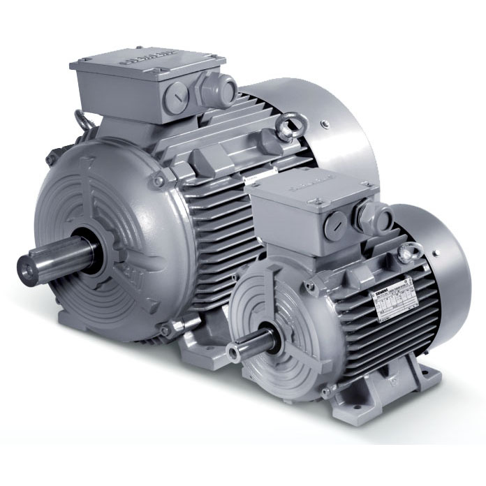
SIMOTICS 1LE0 series of 3 phase asynchronous motors isTotally Enclosed Fan Cooled (TEFC) with IP55 environmentalprotection, and applicable for general purpose use. These motorsare designed and manufactured in accordance with ISO, IECstandards, GB standards.
The 1LE0 series motor is designed for constant or adjustablespeed with continuous duty operation (S1) over a speed range.
Features
- Terminal box on top, and cable entry on right side (viewed from driven end). Variable location of connection boxes and cable entries as option.
- Insulation system is designed for temperature class 155 (F). At rated output with line-fed operation, the motors can be used in temperature class 130 (B).
- Self ventilated motors with radial-flow fans (cooling method IC 411 according to IEC 60034-6) as standard, forced air cool with external separately driven fans as option.
- FS 80 ~ 90 motor donot have eyebolt; FS 100 ~ 355 all motors have 2 eyebolts. Aluminum housing motors FS100~160 have integrated cast eyebolts.
- Frame material: grey cast iron or aluminum alloy.
- Standard color: stone grey (RAL 7030)
- Rated power output: 0.55kW~315kW at 50Hz.
- Available in 2, 4, 6 pole motor (0.75kW and up) with efficiency grade 3 or 2. according to GB18613-2012 and efficiency class IE2 or IE3 (50Hz) according to IEC 60034-30.
- Optimized compact style construction.
- Standard mounting construction according to IEC 60034-7: IM B3, IM B5, IM B35 and etc.
- All motors are designed to IP55 degree of protection (IEC 60034-5) .
- Re-greasing devices for FS1) 280 ~ 355 as standard, and for FS100 ~ 250 as option.
- Reinforced bearings for increased cantilever forces for FS100 ~ 355 as option.
- Winding protections with PTC, PT100 and KTY84-130 as option.
Environmental
-20ºC≤T≤20ºC:100%
20ºC<T≤30ºC:95%
30ºC<T≤40ºC:55%
- Degrees of motor protection IP55 (IEC 60034-5).
- Altitude shall not exceed 1000m above sea-level (IEC 60034-1).
- Allowed air temperature between -20 ºC and 40 ºC (IEC 60034-1).
- Permitted relative humidity:
-20 ºC ≤ T ≤ 20 ºC:100 %
20 ºC < T ≤ 30 ºC:95 %
30 ºC < T ≤ 40 ºC:55 %
For higher coolant temperatures and / or site altitudes higher than 1000 m above sea level, the specified motor output must be reduced by using the factor kHT. The results in an admissible output(Padm) of the motor:
Padm = Prated • KHT
| Site altitude above see level | Site altitude above see level Coolant temperature | |||||
|---|---|---|---|---|---|---|
| < 30 ºC | 30 ~ 40 ºC | 45 ºC | 50 ºC | 55 ºC | 60 ºC | |
| 1000 m | 1.07 | 1.00 | 0.96 | 0.92 | 0.87 | 0.82 |
| 1500 m | 1.04 | 0.97 | 0.93 | 0.89 | 0.84 | 0.79 |
| 2000 m | 1.00 | 0.94 | 0.90 | 0.86 | 0.82 | 0.77 |
| 2500 m | 0.96 | 0.90 | 0.86 | 0.83 | 0.78 | 0.74 |
| 3000 m | 0.92 | 0.86 | 0.82 | 0.79 | 0.75 | 0.70 |
| 3500 m | 0.88 | 0.82 | 0.79 | 0.75 | 0.71 | 0.67 |
| 4000 m | 0.82 | 0.77 | 0.74 | 0.71 | 0.67 | 0.63 |
Reference standards
| Title | IEC standard | Chinese standard |
|---|---|---|
| Rotating electrical machines – Part 1: Rating and performance | IEC 60034-1 | GB 755 |
| Rotating electrical machines – Part 2-1: Standard methods for determining losses and efficiency from tests (excluding machines for traction vehicles) | IEC 60034-2 | GB/T 1032 |
| Rotating electrical machines – Part 5: Degrees of protection provided by the integral design of rotating electrical machines (IP code) - Classification | IEC 60034-5 | GB/T 4942.1 |
| Rotating electrical machines – Part 6: Methods of cooling (IC Code) | IEC 60034-6 | GB/T 1993 |
| Rotating electrical machines – Part 7: Classification of types of construction, mounting arrangements and terminal box position (IM Code) | IEC 60034-7 | GB/T 997 |
| Rotating electrical machines – Part 8: Terminal markings and direction of rotation | IEC 60034-8 | GB/T 1971 |
| Rotating electrical machines – Part 9: Noise limits | IEC 60034-9 | GB 10069.3 |
| Rotating electrical machines – Part 14: Mechanical vibration of certain machines with shaft heights 56 mm and higher – Measurement, evaluation and limits of vibration severity | IEC 60034-14 | GB 10068 |
| Rotating electrical machines – Part 1: Frame numbers 56 to 400 and flange numbers 55 to 1080 | IEC 60072-1 | GB/T 4772.1 |
| Safety requirements of small and medium size rotating electrical machines | GB 14711 | |
| Electrical insulation – Thermal classification | IEC 60085 | GB/T 11021 |
| Classification of environmental conditions Part 2-1: Environmental conditions appearing in nature – Temperature and humidity | IEC 60721-2-1 | GB/T 4797.1 |
| Standard voltages | IEC 60038 | GB/T 156 |
Noise levels
The noise levels are measured in accordance with DIN EN ISO 1680 in a dead room. It is specified as the A-valued measuring-surface sound pressure level Lpfa in dB (A). This is the spatial mean value of the sound pressure levels measured on the measuring surface. The measuring surface is a cube 1 m away from the motor surface. The sound power level is also specified as LWA in dB (A). The following specified values are only valid for totally enclosed fan cooling (cooling method: IC411) motor with no load at 50 Hz with no load, and the tolerance is +3 dB. While motor operating 60 Hz with no load, the values are approximately +4 dB (A) higher.
Vibration
1LE0 rotors are dynamically balanced to severity grade A using a half key. Table below contains the effective vibration values for unloaded motors.
| Vibration grade | Frame size (mm) | 56 ≤ FS ≤ 132 | 160 ≤ FS ≤ 280 | 280 < FS ≤ 355 |
|---|---|---|---|---|
| A | Mounting | Vibration velocity(mm/s) | Vibration velocity(mm/s) | Vibration velocity(mm/s) |
| Free suspension | 1.6 | 2.2 | 2.8 | |
| Rigid mounting | 1.3 | 1.8 | 2.3 | |
| B | Free suspension | 0.7 | 1.1 | 1.8 |
| Rigid mounting | - | 0.9 | 1.5 |
Nameplate
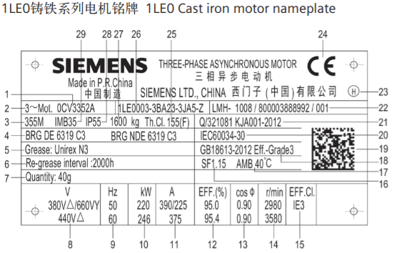

| 1 电动机型号 | Motor type | 16 服务系数 | Service factor |
| 2 电动机类别 | Category of motor | 17 环境温度 | Ambient temperature |
| 3 机座号 | Frame size | 18 能效等级GB | Efficiency class according to GB standard |
| 4 轴承型号 | Bearing type | 19 二维码 | QR code |
| 5 润滑脂型号 | Bearing grease type | 20 IEC标准 | IEC standard |
| 6 再润滑周期 | Re-grease interval | 21 企业标准 | Company standard |
| 7 加注油脂量 | Re-grease quantity | 22 产品序列号 | Product series number |
| 8 额定电压和接线方式 | Rated voltage and connection | 23 平衡方式 | Balance method |
| 9 额定频率 | Rated frequency | 24 CE标识 | CE mark |
| 10 额定功率 | Rated power | 25 热分级 | Thermal class |
| 11 额定电流 | Rated current | 26 订货号 | Order No. |
| 12 效率 | Efficiency | 27 电机重量 | Motor weight |
| 13 功率因数 | Power factor | 28 IP防护等级 | IP protection class |
| 14 额定转速 | Rated speed | 29 安装结构形式 | Mounting type |
| 15 能效等级IEC | Efficiency class according to IEC standard |
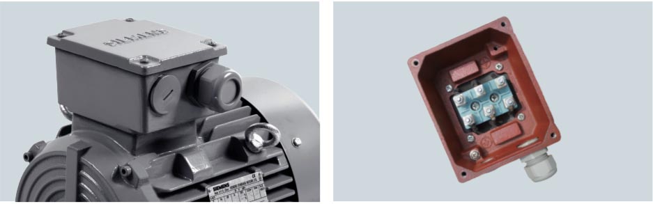
Connection box
The connection box is located on the top of motor housing as standard, and can be rotated by 4×90º to allow for cable entry from each direction. All the connection box have 2 cable entries, one is sealed by the cable gland, and another sealed by screwed plug.
Connection boxes technical data
| Frame Size | Number of mainterminals | Max. allowableauxiliary terminals | Contact screw thread | Max. connectable cross-section(mm²) | Outer cable diameter (sealing range)(mm) | Cable entry size (Gland+Screwed plug) |
|---|---|---|---|---|---|---|
| 80 | 6 | 12 | M4 | 1.5 | 13 ~ 18 | M25×1.5+M16×1.5 |
| 90 | 6 | 12 | 1.5 | |||
| 100 | 6 | 12 | 4 | 18 ~ 25 | M32×1.5+M32×1.5 | |
| 112 | 6 | 12 | 4 | |||
| 132 | 6 | 12 | 6 | |||
| 160 Cast Iron | 6 | 14 | M5 | 16 | 22 ~ 32 | M40×1.5+M40×1.5 |
| 160 AL | 6 | 12 | 16 | 18 ~ 25 | M36×2+M36×2 | |
| 180 | 6 | 14 | 16 | 22 ~ 32 | M40×1.5+M40×1.5 | |
| 200 | 6 | 14 1) | M6 | 25 | 32 ~ 38 | M50×1.5+M50×1.5 |
| 225 | 6 | 14 1) | M8 | 35 | ||
| 250 | 6 | 14 1) | M10 | 120 | 37 ~ 44 | M63×1.5+M63×1.5 |
| 280 | 6 | 14 1) | 120 | |||
| 315 | 6 | 16 1) | M12 | 240 | ||
| 355 | 6 | 24 1) | M16 | 240 | 44 ~ 57 | M72×2+M72×2 |
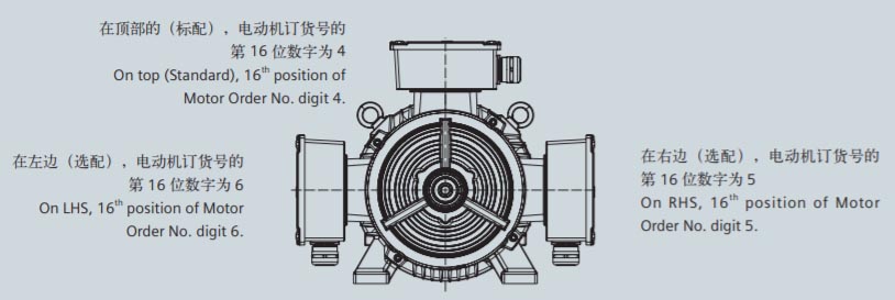
Location of the connection box
Besides standard position, the connection box also can be on the right or left of motor housing. The position of terminal box can be indicated on the 16th digit of motor order code.
The position of connection box is described by viewed from drive end (DE).
- On top (Standard), 16th position of Motor Order No. digit 4.
- On RHS, 16th position of Motor Order No. digit 5.
- On LHS, 16th position of Motor Order No. digit 6.
If there is interfere between the connection box and other components, the connection box can be moved from the drive end (DE) to non-drive end (NDE) (Option code: H08).
Unless stated, otherwise the cable entry is located in the standard position as show in the following illustration. The connection box can also be rotated such that the cable entry is located.
Towards the drive end (DE):Rotation of connection box by 90°, entry from DE, Option code R10. For flange motor (IM B5) from FS80 to FS100, only possible with connection box on NDE (Option code H08).
Towards the non-drive end (NDE):Rotation of connection box by 90°, entry from NDE, Option code R11.
Towards the left side (opposite to Standard):Rotation of connection box by 180°, entry from opposite end, Option code R12.
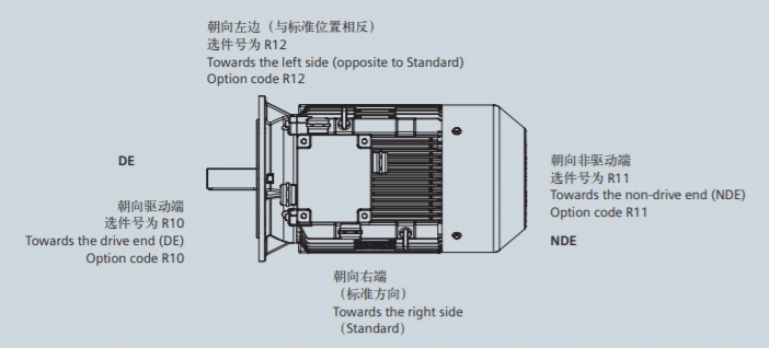
If the position of the connection box (connection box RHS or LHS) is changed, the position of the cable entry must be checked. If necessary, it can be ordered with the corresponding order codes (R10, R11 and R12).
Construction and mounting type
| Construction type | With feet and without flange on the end-shield (DE) | ||||||||
| Mounting type | IM B3FS 80 ~ 355 | IM B6FS 80 ~ 315 | IM B7 FS80 ~ 315 | IM B8FS 80 ~ 315 | IM V5 1)FS 80 ~ 315 | IM V6 2)FS 80 ~ 315 | |||
| Diagram |  |
 |
 |
 |
 |
 |
|||
| Letter, position 14th of Motor code | A | T | U | V | C | D | |||
| Construction type | Without feet and with flange on the end-shield (DE) | With feet and with flange on the end-shield (DE) | |||||||
| Mounting type | IM B5 FS 80 ~ 315 | IM V1 1)FS 80 ~ 355 | IM V3 2)FS 80 ~ 315 | IM B35 FS 80 ~ 355 | IM V15 1)FS 80 ~ 315 | IM V35 2)FS 80 ~ 315 | |||
| Diagram |  |
 |
 |
 |
 |
 |
|||
| Letter, position 14th of Motor code | F | G | H | J | W | Y | |||
| Construction type | Without feet and with C-flange on the end-shield (DE) | With feet and with C-flange on the end-shield (DE) | |||||||
| Mounting type | IM B14 FS 80 ~ 160 | IM V18 1)FS 80 ~ 160 | IM V19 2)FS 80 ~ 160 | IM B34 FS 80 ~ 160 | |||||
| Diagram |  |
 |
 |
 |
|||||
| Letter, position 14th of Motor code | K | M | L | N | |||||
Cooling and ventilation
The 1LE0 standard motors are fitted with an radial flow fan for cooling in accordance with IEC 60034-6 cooling method.
For some special application, separately driven fan should be considered to be configurated.
The use of a separately driven fan is recommended to increase motor utilization at low speed;
When motor speed significantly higher than the synchronous speed, the separately fan is also recommended to be used. It can help reduce the motor noise.
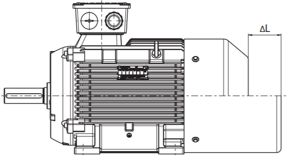
The separately driven fan can be supplied already fitted, Option code F70. When the separately driven fan is mounted, the length of the motor increase by 6L.
| Motor frame size | Voltage (V) | Frequency (Hz) | Rated output (W) | Current (A) | Speed (r/min) | 6L (mm) |
|---|---|---|---|---|---|---|
| 80 | 220Δ / 380Y | 50 | 30 | 0.14/0.08 | 2800 | 60 |
| 90 | 220Δ / 380Y | 50 | 30 | 0.14/0.08 | 2800 | 70 |
| 100 | 220Δ / 380Y | 50 | 52 | 0.21/0.12 | 2800 | 80 |
| 112 | 220Δ / 380Y | 50 | 52 | 0.21/0.12 | 2800 | 90 |
| 132 | 220Δ / 380Y | 50 | 45 | 0.35/0.2 | 1400 | 75 |
| 160 | 220Δ / 380Y | 50 | 45 | 0.35/0.2 | 1400 | 55 |
| 180 | 220Δ / 380Y | 50 | 120 | 1.04/0.6 | 1400 | 65 |
| 200 | 220Δ / 380Y | 50 | 120 | 1.04/0.6 | 1400 | 65 |
| 225 | 220Δ / 380Y | 50 | 120 | 1.04/0.6 | 1400 | 60 |
| 250 | 220Δ / 380Y | 50 | 230 | 1.73/1.0 | 1400 | 80 |
| 280 | 220Δ / 380Y | 50 | 230 | 1.73/1.0 | 1400 | 110 |
| 315 | 220Δ / 380Y | 50 | 370 | 1.91/1.1 | 1250 | 90 |
| 355 | 220Δ / 380Y | 50 | 550 | 2.18/1.26 | 1350 | 100 |
Bearing system
50Hz, and also 220 ~ 260VD/380 ~ 480VY 60Hz. Other voltage supply, possible on request.
1LE0 series motors are supplied with the ball bearing as standard. These bearings are either of the sealed or regreasable type.
For FS80 ~ 160, the floating bearings are assembled; for FS180 ~ 355, floating bearing at DE, and fixed bearing at NDE assembled.
The standard bearing can endure a maximum cantilever force, referred to page 11 - Permissible cantilever forces. If higher cantilever force on the shaft required, the increased cantilever bearing design (Option code: L22) should be considered.
As standard, FS80 ~ 250 motors are not with regreasing device, but FS280 ~ 355 motors with regreasable bearing and regreasing device. If necessary, FS100 ~ 250 motor can be configured with regreasable bearing and regreasing device (Option code: L23).
Bearing Assignment
| Frame size | Pole | Standard design | Increased cantilever-bearing (Option code: L22) | Re-greasing bearing (Option code: L23) | |||||
|---|---|---|---|---|---|---|---|---|---|
| DEbearing | NDE bearing(Horizontal mounting) | NDE bearing(Vertical mounting) | DEbearing | NDE bearing(Horizontal mounting) | NDE bearing(Vertical mounting) | DE bearing | NDE bearing | ||
| 80 | 2, 4, 6 | 6204 2Z C3 | 6204 2Z C3 | 6204 2Z C3 | - | - | - | - | - |
| 90 | 2, 4, 6 | 6205 2Z C3 | 6205 2Z C3 | 6205 2Z C3 | - | - | - | - | - |
| 100 | 2, 4, 6 | 6206 2Z C3 | 6206 2Z C3 | 6206 2Z C3 | 6306 2Z C3 | 6206 2Z C3 | 6206 2Z C3 | 6206 C3 | 6206 C3 |
| 112 | 2, 4, 6 | 6206 2Z C3 | 6206 2Z C3 | 6206 2Z C3 | 6306 2Z C3 | 6206 2Z C3 | 6206 2Z C3 | 6206 C3 | 6206 C3 |
| 132 | 2, 4, 6, 8 | 6208 2Z C3 | 6208 2Z C3 | 6208 2Z C3 | 6308 2Z C3 | 6208 2Z C3 | 6208 2Z C3 | 6208 C3 | 6208 C3 |
| 160 | 2 | 6209 2Z C3 | 6209 2Z C3 | 6209 2Z C3 | 6309 2Z C3 | 6209 2Z C3 | 6209 2Z C3 | 6209 C3 | 6209 C3 |
| 4, 6, 8 | |||||||||
| 180 | 2 | 6210 Z C3 | 6210 Z C3 | 6210 Z C3 | NU210 | 6210 Z C3 | 6210 Z C3 | 6210 C3 | 6210 C3 |
| 4, 6, 8 | |||||||||
| 200 | 2 | 6212 Z C3 | 6212 Z C3 | 6212 Z C3 | NU212 | 6212 Z C3 | 6212 Z C3 | 6212 C3 | 6212 C3 |
| 4, 6, 8 | |||||||||
| 225 | 2 | 6213 Z C3 | 6213 Z C3 | 6213 Z C3 | NU213 | 6213 Z C3 | 6213 Z C3 | 6213 C3 | 6213 C3 |
| 4, 6, 8 | |||||||||
| 250 | 2 | 6215 C3 | 6215 C3 | 7215 AC | NU215 | 6215 C3 | O.R. | 6215 C3 | 6215 C3 |
| 4, 6, 8 | |||||||||
| 280 | 2 | 6317 C3 | 6317 C3 | 7317 AC | NU317 | 6317 C3 | O.R. | ||
| 4, 6, 8 | 6317 C3 | 6317 C3 | NU317 | 6317 C3 | |||||
| 315 | 2 | 6319 C3 | 6319 C3 | 7319 AC | NU319 | 6319 C3 | O.R. | ||
| 4, 6, 8 | 6319 C3 | 6319 C3 | NU319 | 6319 C3 | |||||
| 355 | 2 | 6319 C3 | 6319 C3 | 7319 AC | NU319 | 6319 C3 | O.R. | ||
| 4, 6, 8 | 6322 C3 | 6322 C3 | 7322 AC | NU322 | 6322 C3 | O.R. | |||
Bearing life time (nominal lifetime)
The nominal bearing lifetime is defined according standardized calculation procedures (ISO 281) and is reached or even exceeded for 90% of the bearings when the motors are operated in compliance with the data provide in the catalog. Generally, the bearing lifetime is defined by the bearing size, the bearing load, the operating condition, the speed and the grease lifetime.
The bearing lifetime of motors with horizontal type of construction is at least 40,000 hours if there is no additional axial loading at the coupling output and at least 20,000 hours with the maximum admissible loads. This assumes that the motor is operated at 50Hz.
When the motor runs outside of normal conditions, the bearing life will be reduced, such as the following conditions.
- When 1LE0 motor runs beyond the rated speed, the increase of motor vibration will result in the extra radial and axial force on bearing. This will reduce the life of bearing;
- When the motor vibration increase due to the environment or other equipment, the bearing also will endure more radial and axial force. This also will reduce the life of bearing;
- If the coolant temperature is increased by 10 ºC, the grease lifetime and regreasing interval is halved.
Grease life and re-greasing interval
For permanent lubrication, the bearing grease lifetime is matched to the bearing lifetime. This can, however, only be achieved if the motor is operated in accordance with the catalog specifications.
For motors which can be regreased at defined regreasing intervals, the bearing lifetime can be extended and/or unfavorable factors such as temperature, mounting conditions, speed, bearing size and mechanical load can be compensated.
Grease life (Horizontal installation)
| Frame size | Poles | Grease lifetime up to CT 40 ºC 1) |
|---|---|---|
| Grease for permanent lubrication bearing | ||
| 80 ~ 250 | 2,4,6,8 | 20000 (or) 40000 2) |
| Grease for regreasable bearing | ||
| 100 ~ 160 | 2,4,6,8 | 8000 (h) |
| 180 ~ 250 | 2 | 4000(h) |
| 180 ~ 250 | 4,6,8 | 8000 (h) |
| 280 ~ 315 | 2 | 3000 (h) |
| 280 ~ 315 | 4,6,8 | 5000(h) |
| 355 | 2 | 2000 (h) |
| 355 | 4,6,8 | 4000 (h) |
Permissible cantilever forces on DE shaft

In order to calculate the admissible cantilever forces for a radial load, the line of force (i.e. the centerline of the pulley) of the cantilever force FQ(N) must lie within the free shaft extension (dimension x).Dimension x [mm] is the distance between the point of application of force FQ and the shaft shoulder. Dimension xmax. Corresponds to the length of the shaft extension. Total cantilever force is calculated using the following equation.
FQ = c • FU
The pre-tension factor c is a value gained from experience from the belt manufacturer. The following approximate value can be assumed.
For normal flat leather belts with an idler pulley, c = 2.
For v-belts, c = 2 to 2.5.
For special synthetic belts (depending on the type and load), c = 2 to 2.5.
The circumferential force FU (N) is calculated using the following equation.
F = 2 • 107P/(n×D)
FU circumferential force in N
FU:circumferential force in N
P:rated motor power (transmitted power) in kW
n:rated motor speed
D:pulleys in mm.
The table below contains the permissible Radial Force values in Newtons with the assumption of zero axial forces.
| Frame size | Number of poles | Admissible cantilever force 1) | |
|---|---|---|---|
| for x0 N | for xmax N | ||
| 80M | 2 | 620 | 510 |
| 4 | 790 | 640 | |
| 6 | 910 | 740 | |
| 90S90L | 2 | 700 | 560 |
| 4 | 880 | 720 | |
| 6 | 1,020 | 820 | |
| 100L | 2 | 980 | 790 |
| 4 | 1,230 | 990 | |
| 6 | 1,420 | 1,140 | |
| 112M | 2 | 980 | 790 |
| 4 | 1,230 | 990 | |
| 6 | 1,420 | 1,140 | |
| 132S132M | 2 | 1,440 | 1,120 |
| 4 | 1,820 | 1,420 | |
| 6 | 2,080 | 1,630 | |
| 8 | 2300 | 1800 | |
| 160M160L | 2 | 1,560 | 1,240 |
| 4 | 1,970 | 1,570 | |
| 6 | 2,260 | 1,800 | |
| 8 | 2500 | 1980 | |
| 180M180L | 2 | 1,820 | 1,470 |
| 4 | 2,300 | 1,900 | |
| 6 | 2,630 | 2,150 | |
| 8 | 4,800 | 3,880 | |
| 200L | 2 | 2,650 | 2,230 |
| 4 | 3,350 | 2,800 | |
| 6 | 3,850 | 3,230 | |
| 8 | 6,520 | 5,380 | |
| 225S225M | 2 | 3,000 | 2,540 |
| 4 | 3,700 | 3,000 | |
| 6 | 4,250 | 3,470 | |
| 8 | 7,300 | 5,790 | |
| 250M | 2 | 3,150 | 2,620 |
| 4 | 3,950 | 3,280 | |
| 6 | 4,600 | 3,820 | |
| 8 | 8,110 | 6,620 | |
| 280S280M | 2 | 6,600 | 5,550 |
| 4 | 8,300 | 6,950 | |
| 6 | 9,650 | 8,120 | |
| 8 | 11,600 | 9,800 | |
| 315S315M315L | 2 | 7,100 | 6,200 |
| 4 | 8,700 | 7,250 | |
| 6 | 10,000 | 8,500 | |
| 8 | 14,300 | 10,400 | |
| 355M355L | 2 | 6,800 | 6,000 |
| 4 | 11,500 | 10,000 | |
| 6 | 13,200 | 11,600 | |
| 8 | 19,000 | 15,600 | |
| Frame size | Number of poles | Admissible cantilever force 1) | |
|---|---|---|---|
| for x0 N | for xmax N | ||
| 80M | 2 | -2) | -2) |
| 4 | -2) | -2) | |
| 6 | -2) | -2) | |
| 90S90L | 2 | -2) | -2) |
| 4 | -2) | -2) | |
| 6 | -2) | -2) | |
| 100L | 2 | 1,480 | 1,220 |
| 4 | 1,870 | 1,540 | |
| 6 | 2,140 | 1,720 | |
| 112M | 2 | 1,480 | 1,220 |
| 4 | 1,870 | 1,540 | |
| 6 | 2,140 | 1,720 | |
| 132S132M | 2 | 2,100 | 1,700 |
| 4 | 2,720 | 2,170 | |
| 6 | 3,100 | 2,420 | |
| 8 | 3,400 | 2,700 | |
| 160M160L | 2 | 2,650 | 2,120 |
| 4 | 3,300 | 2,600 | |
| 6 | 3,750 | 2,900 | |
| 8 | 3,750 | 2,900 | |
| 180M180L | 2 | 3,300 | 2,700 |
| 4 | 4,200 | 3,400 | |
| 6 | 4,750 | 3,900 | |
| 8 | 6,950 | 4,050 | |
| 200L | 2 | 5,000 | 4,200 |
| 4 | 6,330 | 5,320 | |
| 6 | 7,250 | 6,080 | |
| 8 | 10,100 | 7,400 | |
| 225S225M | 2 | 5,650 | 4,800 |
| 4 | 6,950 | 5,600 | |
| 6 | 7,900 | 6,500 | |
| 8 | 11,300 | 7,350 | |
| 250M | 2 | 6,700 | 5,600 |
| 4 | 8,500 | 7,000 | |
| 6 | 9,500 | 7,800 | |
| 8 | 12,800 | 10,500 | |
| 280S280M | 2 | 11,500 | 9,500 |
| 4 | 17,000 | 14,000 | |
| 6 | 20,000 | 17,000 | |
| 8 | 22,000 | 17,500 | |
| 315S315M315L | 2 | 14,600 | 12,300 |
| 4 | 20,000 | 16,500 | |
| 6 | 23,000 | 19,000 | |
| 8 | 25,000 | 20,000 | |
| 355M355L | 2 | 15,800 | 14,000 |
| 4 | 22,000 | 19,000 | |
| 6 | 25,000 | 22,000 | |
| 8 | 29,000 | 26,000 | |
Rated Output
1LE0 motors rated output powers means that the motor runs under continuous duty S1 (IEC 60034 - 1) operation when operated at ambient temperature from -20 ºC to 40 ºC and at altitudes of up to 1000 m over sea.
Voltage and Frequency
IEC 60034-1 differentiates between Category A (combination of voltage deviation ±5 % and frequency deviation ±2 %) and Category B (combination of voltage deviation ±10 % and frequency deviation +3 % / -5 %) for voltage and frequency fluctuations. The motors can supply their rated torque in both Category A and B. In Category A, the temperature rise is approximately 10 K higher than during normal operation.
| Standard60034 - 1 | CategoryA | CategoryB |
|---|---|---|
| Voltage deviation | ±5 % | ±10 % |
| Frequency deviation | ±2 % | +3 % / -5 % |
| According to the standard, longer operation is not recommended for Category B. | ||
Tolerance for electrical data
- Efficiencyηat
Prated ≤ 150 kW: - 0.15 x (1 – η)
Prated > 150 kW: - 0.10 x (1 – η)
With η being a decimal number - Power factor - (1 – cosφ) / 6
Minimum absolute value: 0.02
Maximum absolute value: 0.07 - Slip ±20 % (for motors < 1 kW ±30 % is admissible)
- Locked-rotor current +20 %
- Locked-rotor torque -15 % to +25 %
- Breakdown torque -10 %
- Moment of inertia ±10 %
Overload times
According to IEC60034, 1LE0 series motors are designed to with stand overload capacity of 1.5 times rated current for 2 minutes at rated voltage and frequency.
Insulation system
The insulation system of 1LE0 results in high reliability, a long servicelife and high resistance to stress, for example, during starting orunder overload conditions.
1LE0 series motors are designed for temperature class 155 (F). Atrated output with line-fed operation, the motors can be used intemperature class 130 (B).
Motor protection
Motor thermal protection means to use of thermal protectors and thermal detectors incorporated into the stator windings or placed in other suitable positions in motor in order to protect them against serious damage due to thermal overloads.
The order variants for motor protection are coded with letters in the 15th position of the Motor Order No., or ordered with Option code. Some protection method about winding protection and bearing protection are shown in the following.
Winding protection
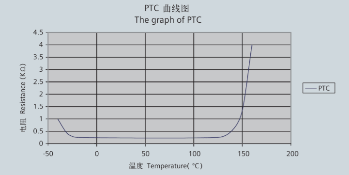
PTC thermistors protection
The most comprehensive protection against thermal overloading of the motor is provided by PTC thermistors (thermistor motor protection) installed in the motor winding. The temperature of the winding can be accurately monitored thanks to its lowheating capacity and the excellent heat contact with the winding. When
a limit temperature is reached (nominal tripping temperature), the resistance of PTC thermistors will have a step change. This is evaluated by a tripping unit and can be used to open auxiliary circuits.
The PTC thermistors themselves cannot be subjected to high currents and voltages. This would result in destruction of the semiconductor. The switching hysteresis of the PTC thermistor and tripping unit is low, which supports fast restarting of the drive.
Motors with this type of protection are recommended for heavy duty starting, switching duty, extreme changes in load, high ambient temperatures or fluctuating supply systems.
- Motor winding is protected with PTC thermistors with 3 embedded temperature sensors for tripping. Connection be done through 2 auxiliary terminals in the connection box. 15th position of Motor Order No. letter B.
- Motor winding is protected with two sets of three temperature sensors, one set is for warning, another set for tripping. The warning temperature is 145 ºC, and tripping temperature is 155 ºC. Connection be done through 4 auxiliary terminals in the connection box. 15th position of Motor Order No. letter C.
KTY84-130 temperature sensor protection
When 1LE0 with converter fed operation, KTY84-30 is recommended to be configured for winding protection. The following chart show the characteristic of KTY84-30.

Some converters from Siemens determine the motor temperature using the resistance of the temperature sensor. They can be set to a required temperature for alarm and tripping.
1LE0 Motor winding with embedded temperature detector sensor KTY 84-130. Two auxiliary terminals are provided in the connection box. 15th position of Motor Order No. letter F.
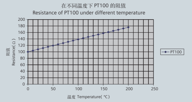
PT100 resistance thermometers protection
PT100 thermometers are a high precision, high sensitivity, better linear temperature resistance, more stable performance, and high reliability sensor, whose characteristics are as following.
2 alternatives of PT100
- Installation of 3 PT100 resistance thermometers. Connection be done through 6 auxiliary terminals in the connection box. 15th position of Motor Order No. letter H.
- Installation of 6 PT100 resistance thermometers. Connection be done through 12 auxiliary terminals in the connection box. 15th position of Motor Order No. letter J.
Bearing protection
1LE0 motors bearing has no protection as standard. For some severe application, such as high load, high coolant temperature and etc., the bearing is recommended to be protected. The bearing is protected through thermometers screwed into the bearing plates of motor driven end (DE) and non-drive-end (NDE). The wires are routed through the main connection box.
Installation of 2 PT100 screwed-in resistance thermometers for 1LE0 motor bearings, Option code: Q5A. Connection be done through 4 auxiliary terminals in the connection box.
Anti-condensation heater
Motors whose windings are at risk of condensation due to the climatic conditions, e.g. inactive motors in humid atmospheres or motors that are subjected to widely fluctuating temperatures can be equipped with anti-condensation heaters (Option code: Q04), 2 auxiliary terminals in connection box are needed.”
Anti-condensation heaters must be switched off during operation. When motor shut down, the heaters must be switched on.
| Frame size | Power(W) | Vlotage |
|---|---|---|
| 80 ~ 90 | 20 | 220 V |
| 100 ~ 112 | 30 | 220 V |
| 132 ~ 160 | 40 | 220 V |
| 180 ~ 200 | 50 | 220 V |
| 225 ~ 280 | 60 | 220 V |
| 315 | 80 | 220 V |
| 355 | 100 | 220 V |
Converter fed application
1LE0 motors are suitable for pumps, fans, compressors, texitle machine and mechanical machine applications where variable or constant speed is required.
In application where the motor is driven by a converter, the degree of electrical interference depends on the type of converter used (type, number of IGBTs, interference suppression measures, and manufacturer), cabling, distance and application requirements.
The installation guidelines of the converter manufacturer with regards to electromagnetic compatibility must be considered at all times during the design and implementation phases.
At rated output with converter fed operation, the motors will be used in temperature class 155 (F). To prevent damage as a result of bearing currents, insulated bearings are recommended to be assembled for frame size 250 and above. Please inquire Siemens about the detailed information of insulated bearing.
Converter-fed operation
The standard insulation of the 1LE0 motors is designed such that operation is possible on the converter at mains voltage up to 460 V.
1LE0 motors are capable for converter-fed operation with certain characteristics load, of which the load torque characteristics is referred in the following diagram:

By usage with admissible torque and below, the motor can be operated with self cooling; by usage over the admissible torque line, the motor with forced ventilation is needed.
At operating speeds above rated speed the noise and vibration levels increase and the bearing life time reduce. Attention should be paid to the re-greasing intervals and the grease service life.
For converter-fed operation with frequencies greater than 60 Hz special balancing is required for compliance with the specified limit values.
| Frame Size | 2 pole | 4 pole | 6 pole | 8 pole | ||||
| Max. rpm | fmax | Max. rpm | fmax | Max. rpm | fmax | Max. rpm | fmax | |
| 80 | 5200 | 87 | 3600 | 120 | 2400 | 120 | 1800 | 120 |
| 90 | 5200 | 87 | 3600 | 120 | 2400 | 120 | 1800 | 120 |
| 100 | 5200 | 87 | 3600 | 120 | 2400 | 120 | 1800 | 120 |
| 112 | 5200 | 87 | 3600 | 120 | 2400 | 120 | 1800 | 120 |
| 132 | 4500 | 75 | 2700 | 90 | 2400 | 120 | 1800 | 120 |
| 160 | 4500 | 75 | 2700 | 90 | 2400 | 120 | 1800 | 120 |
| 180 | 4500 | 75 | 2700 | 90 | 2400 | 120 | 1800 | 120 |
| 200 | 4500 | 75 | 2300 | 77 | 1800 | 90 | 1400 | 93 |
| 225 | 3600 | 60 | 2300 | 77 | 1800 | 90 | 1400 | 93 |
| 250 | 3600 | 60 | 2300 | 77 | 1800 | 90 | 1400 | 93 |
| 280 | 3600 | 60 | 2300 | 77 | 1800 | 90 | 1400 | 93 |
| 315 | 3600 | 60 | 2300 | 77 | 1800 | 90 | 1400 | 93 |
| 355 | 3600 | 60 | 2300 | 77 | 1800 | 90 | 1400 | 93 |
Voltage withstand levels
The dielectric stress of the winding insulation is determined by:
- the peak voltage, rise time and frequency of the impulses produced by the converter.
- the characteristics and the length of the connection leads between the converter and motor.
- the winding construction and other system parameters, especially the voltages between the different parts of the winding and the ground represent dielectric stress at the insulation system.
The standard insulation of the 1LE0 motors is designed to withstand voltage peak and rise time which is showed in the diagram:
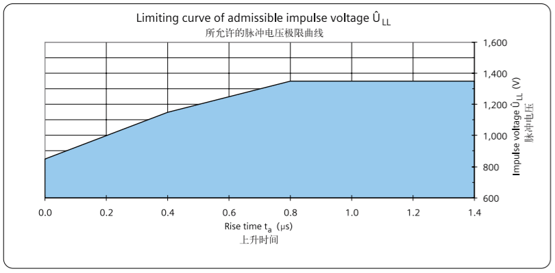
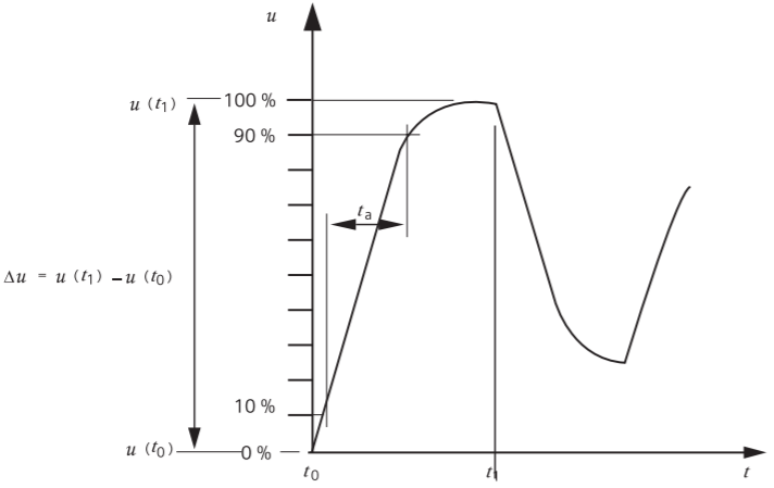
The values refer to standard IEC 60034-17 and GB/T 20161-2008.
Order No. and Motor Type
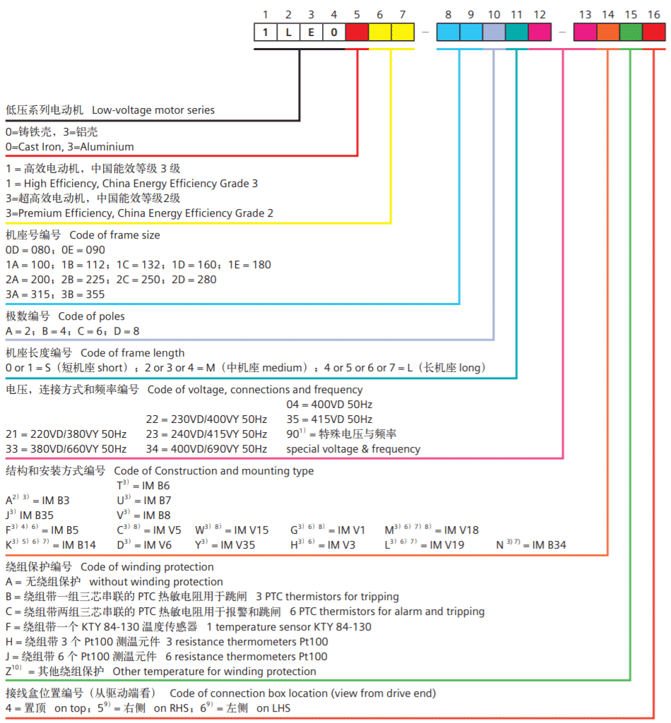
Foot note:
- 1) Order other voltages with voltage code 90 and the corresponding Option code (see under "Option") .
- 2) The types of construction IM B6/7/8, IM V6 and IM V5 without protective cover are also possible as long as no condensation drainage holes (Order code: H03) and no stamping of these types of construction on the rating plate are required. As standard, the type of construction IM B3 is then stamped on the rating plate.
- 3) The type of construction is stamped on the rating plate. When
- ordering with condensation drainage holes (order code H03), it is absolutely necessary to specify the type of construction for the exact position of the condensation drainage holes during manufacture.
- 4) The types of construction IM V1 and IM V3 without protective
- cover are also possible as long as no condensation drainage holes (Order code: H03) and no stamping of these types of construction on the rating plate are required. As standard, the type of construction IM B5 is then stamped on the rating plate.
- 5) The types of construction IM V19 and IM V18 without protective
- cover are also possible as long as no condensation drainage holes (Order code: H03) and no stamping of these types of construction on the rating plate are required. As standard, the type of construction IM B14 is then stamped on the rating plate.
- 6) For motor with IM B5, IM V1, IM V3, IM B14, IM V18 and IM V19
- construction and mounting type, the 16th digit of motor order No. must be "4";
- 7) Only for FS80 ~ 160.
- 8) Without canopy, for protective cover with canopy needed Option code H00.
- 9) Cable entry on connection box towards the non-drive.
- 10) Please specially consult with Siemens.
Order No. example:
IE2, Low voltage three phase cast iron motor
4-pole, 15 kW, IM B5, 380VD/660VY 50 Hz, IP55, connection box on top and cable entry at right side (view from DE), with separately driven fan.
Motor order code: 1LE0001-1DB43-3FA4-Z F70
Technical data table
| Frame Size | Rated Output (50Hz) | Rated Output (60Hz) | Order No. | Rated Speed | Effeciency at (50 HZ) 4/4 load | Effeciency at (50 HZ) 3/4 load | Power factor (50Hz) | Rated current (50Hz) |
|---|---|---|---|---|---|---|---|---|
| kW | kW | rpm | % | % | A | |||
| 3000rpm 2-pole | ||||||||
| 220VD/380VY 50 HZ | ||||||||
| 80M | 0.75 | 0.86 | 1LE0001-0DA22-1××× | 2795 | 77.4 | 78.5 | 0.84 | 1.75 |
| 80M | 1.1 | 1.3 | 1LE0001-0DA32-1××× | 2835 | 79.6 | 80.6 | 0.84 | 2.50 |
| 90S | 1.5 | 1.75 | 1LE0001-0EA02-1××× | 2890 | 81.3 | 81.7 | 0.84 | 3.35 |
| 90L | 2.2 | 2.55 | 1LE0001-0EA42-1××× | 2890 | 83.2 | 83.7 | 0.85 | 4.75 |
| 100L | 3 | 3.45 | 1LE0001-1AA42-1××× | 2885 | 84.6 | 85.1 | 0.84 | 6.4 |
| 3000rpm 2-pole | ||||||||
| 380VD/660VY 50 HZ | ||||||||
| 112M | 4 | 4.6 | 1LE0001-1BA23-3××× | 2930 | 85.8 | 86.6 | 0.86 | 8.2 |
| 132S | 5.5 | 6.3 | 1LE0001-1CA03-3××× | 2930 | 87 | 87.6 | 0.87 | 11.0 |
| 132S | 7.5 | 8.6 | 1LE0001-1CA13-3××× | 2930 | 88.1 | 88.8 | 0.89 | 14.5 |
| 160M | 11 | 12.6 | 1LE0001-1DA23-3××× | 2935 | 89.4 | 90.1 | 0.86 | 21.5 |
| 160M | 15 | 17.3 | 1LE0001-1DA33-3××× | 2935 | 90.3 | 91 | 0.86 | 29.5 |
| 160L | 18.5 | 21.3 | 1LE0001-1DA43-3××× | 2935 | 90.9 | 91.7 | 0.89 | 34.5 |
| 180M | 22 | 24.5 | 1LE0001-1EA23-3××× | 2935 | 91.3 | 91.8 | 0.87 | 42.0 |
| 200L | 30 | 33.5 | 1LE0001-2AA43-3××× | 2955 | 92 | 92.3 | 0.86 | 58 |
| 200L | 37 | 41.5 | 1LE0001-2AA53-3××× | 2955 | 92.5 | 92.8 | 0.88 | 69 |
| 225M | 45 | 51 | 1LE0001-2BA23-3××× | 2965 | 92.9 | 93.1 | 0.88 | 84 |
| 250M | 55 | 62 | 1LE0001-2CA23-3××× | 2970 | 93.2 | 93.2 | 0.88 | 102 |
| 280S | 75 | 84 | 1LE0001-2DA03-3××× | 2975 | 93.8 | 93.8 | 0.87 | 140 |
| 280M | 90 | 101 | 1LE0001-2DA23-3××× | 2978 | 94.1 | 94.1 | 0.87 | 167 |
| 315S | 110 | 123 | 1LE0001-3AA03-3××× | 2982 | 94.3 | 94.3 | 0.90 | 197 |
| 315M | 132 | 148 | 1LE0001-3AA23-3××× | 2982 | 94.6 | 94.6 | 0.91 | 235 |
| 315L | 160 | 180 | 1LE0001-3AA53-3××× | 2982 | 94.8 | 95.1 | 0.92 | 280 |
| 315L | 185 | 207 | 1LE0001-3AA63-3××× | 2982 | 95 | 95.3 | 0.92 | 320 |
| 315L | 200 | 224 | 1LE0001-3AA73-3××× | 2982 | 95 | 95.3 | 0.92 | 350 |
| 355M | 220 | 246 | 1LE0001-3BA23-3××× | 2985 | 95.0 | 94.7 | 0.90 | 390 |
| 355M | 250 | 280 | 1LE0001-3BA33-3××× | 2985 | 95.0 | 94.7 | 0.90 | 445 |
| 355L | 280 | 314 | 1LE0001-3BA53-3××× | 2985 | 95.0 | 95.1 | 0.91 | 490 |
| 355L | 315 | 353 | 1LE0001-3BA63-3××× | 2985 | 95.0 | 95.0 | 0.91 | 550 |
| Order No. | Rated torque | Starting current/ Rated current | Starting torque/ Rated torque | Max torque/ Rated torque | Moment of inertia (J) | Weight IMB3 | Noise |
|---|---|---|---|---|---|---|---|
| Nm | ILR / Irated | TLR / Trated | Tmax / Trated | kgm² | kg | Lpfa/LWA | |
| 3000rpm 2-pole | |||||||
| 220VD/380VY 50 HZ | |||||||
| 1LE0001-0DA22-1××× | 2.6 | 5.6 | 2.4 | 2.4 | 0.00080 | 14 | 53 / 65 |
| 1LE0001-0DA32-1××× | 3.7 | 6 | 2.8 | 3.2 | 0.0012 | 15 | 53 / 65 |
| 1LE0001-0EA02-1××× | 5.0 | 6.5 | 2.4 | 3.1 | 0.0021 | 19 | 60 / 72 |
| 1LE0001-0EA42-1××× | 7.3 | 7.2 | 2.6 | 3.5 | 0.0026 | 22 | 60 / 72 |
| 1LE0001-1AA42-1××× | 9.9 | 7.5 | 4 | 4.5 | 0.0036 | 34 | 62 / 74 |
| 3000rpm 2-pole | |||||||
| 380VD/660VY 50 HZ | |||||||
| 1LE0001-1BA23-3××× | 13.0 | 7.5 | 2.2 | 2.9 | 0.0064 | 40 | 63 / 75 |
| 1LE0001-1CA03-3××× | 17.9 | 7.5 | 2.2 | 2.9 | 0.014 | 56 | 69 / 82 |
| 1LE0001-1CA13-3××× | 24.4 | 7.5 | 2.3 | 2.9 | 0.017 | 62 | 69 / 82 |
| 1LE0001-1DA23-3××× | 35.8 | 7.5 | 2.2 | 2.9 | 0.031 | 96 | 71 / 84 |
| 1LE0001-1DA33-3××× | 48.8 | 7.5 | 2.4 | 3.2 | 0.038 | 106 | 71 / 84 |
| 1LE0001-1DA43-3××× | 60.2 | 7.5 | 2.4 | 3.2 | 0.046 | 125 | 71 / 84 |
| 1LE0001-1EA23-3××× | 71.6 | 7.6 | 2.5 | 3.2 | 0.072 | 152 | 72 / 85 |
| 1LE0001-2AA43-3××× | 97.0 | 7.5 | 2.5 | 3.2 | 0.13 | 229 | 74 / 87 |
| 1LE0001-2AA53-3××× | 119.6 | 7.5 | 2.5 | 3.2 | 0.15 | 245 | 74 / 87 |
| 1LE0001-2BA23-3××× | 144.9 | 7.9 | 2.5 | 3.1 | 0.24 | 307 | 75 / 89 |
| 1LE0001-2CA23-3××× | 176.9 | 7.5 | 2.5 | 3 | 0.42 | 333 / 378* | 75 / 89 |
| 1LE0001-2DA03-3××× | 240.8 | 7.5 | 2.8 | 3 | 0.75 | 550 | 77 / 91 |
| 1LE0001-2DA23-3××× | 288.6 | 7.5 | 3 | 3.1 | 0.88 | 570 | 77 / 91 |
| 1LE0001-3AA03-3××× | 352.3 | 7.5 | 2.2 | 2.6 | 1.4 | 740 | 81 / 95 |
| 1LE0001-3AA23-3××× | 422.7 | 7.5 | 2.3 | 2.9 | 1.7 | 855 | 81 / 95 |
| 1LE0001-3AA53-3××× | 512.4 | 7.5 | 2.5 | 2.8 | 1.9 | 970 | 81 / 95 |
| 1LE0001-3AA63-3××× | 592.5 | 7.5 | 2.5 | 2.8 | 2.3 | 1080 | 81 / 95 |
| 1LE0001-3AA73-3××× | 640.5 | 7.5 | 2.5 | 2.8 | 2.3 | 1090 | 81 / 95 |
| 1LE0001-3BA23-3××× | 704 | 7.0 | 2.0 | 2.6 | 2.5 | 1410 | 86 / 101 |
| 1LE0001-3BA33-3××× | 800 | 7.4 | 2.3 | 2.8 | 2.7 | 1480 | 86 / 101 |
| 1LE0001-3BA53-3××× | 896 | 7.0 | 2.2 | 2.6 | 3 | 1550 | 88 / 103 |
| 1LE0001-3BA63-3××× | 1008 | 7.4 | 2.5 | 2.8 | 3.3 | 1720 | 88 / 103 |
| Frame Size | Rated Output (50Hz) | Rated Output (60Hz) | Order No. | Rated Speed | Effeciency at (50 HZ) 4/4 load | Effeciency at (50 HZ) 3/4 load | Power factor (50Hz) | Rated current (50Hz) |
|---|---|---|---|---|---|---|---|---|
| kW | kW | rpm | % | % | A | |||
| 1500rpm 4-pole | ||||||||
| 220VD/380VY 50 HZ | ||||||||
| 80M | 0.55 | 0.63 | 1LE0001-0DB22-1××× | 1425 | 74.0 | 74.7 | 0.8 | 1.40 |
| 80M | 0.75 | 0.86 | 1LE0001-0DB32-1××× | 1440 | 79.6 | 79.6 | 0.75 | 1.90 |
| 90S | 1.1 | 1.3 | 1LE0001-0EB02-1××× | 1440 | 81.4 | 81.4 | 0.75 | 2.75 |
| 90L | 1.5 | 1.75 | 1LE0001-0EB42-1××× | 1435 | 82.8 | 82.8 | 0.76 | 3.60 |
| 100L | 2.2 | 2.55 | 1LE0001-1AB42-1××× | 1435 | 84.3 | 85 | 0.79 | 5.0 |
| 100L | 3 | 3.45 | 1LE0001-1AB52-1××× | 1435 | 85.5 | 86.3 | 0.79 | 6.7 |
| 1500rpm 4-pole | ||||||||
| 380VD/660VY 50 HZ | ||||||||
| 112M | 4 | 4.6 | 1LE0001-1BB23-3××× | 1445 | 86.6 | 87.1 | 0.79 | 8.9 |
| 132S | 5.5 | 6.3 | 1LE0001-1CB03-3××× | 1460 | 87.7 | 88.2 | 0.79 | 12.1 |
| 132M | 7.5 | 8.6 | 1LE0001-1CB23-3××× | 1460 | 88.7 | 89.4 | 0.82 | 15.7 |
| 160M | 11 | 12.6 | 1LE0001-1DB23-3××× | 1465 | 89.8 | 90.4 | 0.84 | 22.0 |
| 160L | 15 | 17.3 | 1LE0001-1DB43-3××× | 1465 | 90.6 | 91.3 | 0.85 | 29.5 |
| 180M | 18.5 | 21.3 | 1LE0001-1EB23-3××× | 1465 | 91.2 | 91.8 | 0.85 | 36.5 |
| 180L | 22 | 24.5 | 1LE0001-1EB43-3××× | 1465 | 91.6 | 92.3 | 0.85 | 43.0 |
| 200L | 30 | 33.5 | 1LE0001-2AB43-3××× | 1470 | 92.3 | 92.9 | 0.85 | 58 |
| 225S | 37 | 41.5 | 1LE0001-2BB03-3××× | 1475 | 92.7 | 93.2 | 0.86 | 71 |
| 225M | 45 | 51 | 1LE0001-2BB23-3××× | 1475 | 93.1 | 93.5 | 0.87 | 84 |
| 250M | 55 | 62 | 1LE0001-2CB23-3××× | 1480 | 93.5 | 93.9 | 0.86 | 104 |
| 280S | 75 | 84 | 1LE0001-2DB03-3××× | 1485 | 94 | 94.3 | 0.87 | 139 |
| 280M | 90 | 101 | 1LE0001-2DB23-3××× | 1485 | 94.2 | 94.3 | 0.87 | 167 |
| 315S | 110 | 123 | 1LE0001-3AB03-3××× | 1488 | 94.5 | 94.5 | 0.86 | 205 |
| 315M | 132 | 148 | 1LE0001-3AB23-3××× | 1486 | 94.7 | 94.7 | 0.88 | 240 |
| 315L | 160 | 180 | 1LE0001-3AB53-3××× | 1488 | 94.9 | 94.9 | 0.88 | 290 |
| 315L | 185 | 207 | 1LE0001-3AB63-3××× | 1488 | 95.1 | 95.1 | 0.88 | 335 |
| 315L | 200 | 224 | 1LE0001-3AB73-3××× | 1488 | 95.1 | 95.1 | 0.88 | 365 |
| 355M | 220 | 246 | 1LE0001-3BB23-3××× | 1490 | 95.1 | 95.2 | 0.89 | 395 |
| 355M | 250 | 280 | 1LE0001-3BB33-3××× | 1490 | 95.1 | 95.2 | 0.89 | 450 |
| 355L | 280 | 314 | 1LE0001-3BB53-3××× | 1490 | 95.1 | 95.3 | 0.89 | 500 |
| 355L | 315 | 353 | 1LE0001-3BB63-3××× | 1490 | 95.1 | 95.2 | 0.89 | 570 |
| Order No. | Rated torque (50 HZ) | Starting current/ Rated current | Starting torque/ Rated torque | Max torque/ Rated torque | Moment of inertia (J) | Weight IMB3 | Noise |
|---|---|---|---|---|---|---|---|
| Nm | ILR / Irated | TLR / Trated | Tmax / Trated | kgm² | kg | Lpfa/LWA | |
| 1500rpm 4-pole | |||||||
| 220VD/380VY 50 HZ | |||||||
| 1LE0001-0DB22-1××× | 3.7 | 6 | 2 | 2.7 | 0.0021 | 16 | 45 / 57 |
| 1LE0001-0DB32-1××× | 5.0 | 6.5 | 2.8 | 3.5 | 0.0027 | 16.5 | 45 / 57 |
| 1LE0001-0EB02-1××× | 7.3 | 7 | 2.8 | 3.5 | 0.0041 | 19.5 | 47 / 59 |
| 1LE0001-0EB42-1××× | 9.9 | 7 | 3 | 3.8 | 0.0047 | 23 | 47 / 59 |
| 1LE0001-1AB42-1××× | 14.6 | 7 | 3 | 3.2 | 0.0081 | 32 | 55 / 67 |
| 1LE0001-1AB52-1××× | 20.0 | 7 | 3 | 3.2 | 0.010 | 34 | 55 / 67 |
| 1500rpm 4-pole | |||||||
| 380VD/660VY 50 HZ | |||||||
| 1LE0001-1BB23-3××× | 26.4 | 7.1 | 2.7 | 3.1 | 0.011 | 45 | 55 / 67 |
| 1LE0001-1CB03-3××× | 36.0 | 7.5 | 2.5 | 3.1 | 0.021 | 61 | 57 / 70 |
| 1LE0001-1CB23-3××× | 49.1 | 7.7 | 2.7 | 3.2 | 0.029 | 73 | 57 / 70 |
| 1LE0001-1DB23-3××× | 71.7 | 7.5 | 2.5 | 3.1 | 0.051 | 103 | 60 / 73 |
| 1LE0001-1DB43-3××× | 97.8 | 7.8 | 2.7 | 3.2 | 0.066 | 130 | 60 / 73 |
| 1LE0001-1EB23-3××× | 120.6 | 7.3 | 2.5 | 3.2 | 0.13 | 165 | 61 / 74 |
| 1LE0001-1EB43-3××× | 143.4 | 7.3 | 2.4 | 3.2 | 0.14 | 180 | 64 / 77 |
| 1LE0001-2AB43-3××× | 194.9 | 7.3 | 2.7 | 3.2 | 0.22 | 238 | 67 / 80 |
| 1LE0001-2BB03-3××× | 239.6 | 7.3 | 2.7 | 3.2 | 0.45 | 298 | 67 / 81 |
| 1LE0001-2BB23-3××× | 291.4 | 7.3 | 2.7 | 3.2 | 0.51 | 322 | 67 / 81 |
| 1LE0001-2CB23-3××× | 354.9 | 7.5 | 3.1 | 3.5 | 0.80 | 365 / 410* | 68 / 82 |
| 1LE0001-2DB03-3××× | 482.3 | 7.5 | 2.7 | 3.1 | 1.4 | 555 | 70 / 84 |
| 1LE0001-2DB23-3××× | 578.8 | 7.5 | 2.7 | 3.1 | 1.5 | 610 | 70 / 84 |
| 1LE0001-3AB03-3××× | 706.0 | 7.3 | 2.8 | 2.9 | 2.2 | 750 | 72 / 86 |
| 1LE0001-3AB23-3××× | 848.3 | 7.3 | 2.5 | 2.7 | 2.5 | 875 | 72 / 86 |
| 1LE0001-3AB53-3××× | 1026.9 | 7.4 | 3 | 2.9 | 3.0 | 960 | 72 /86 |
| 1LE0001-3AB63-3××× | 1187.3 | 7.4 | 3 | 3 | 3.6 | 1070 | 74 / 88 |
| 1LE0001-3AB73-3××× | 1283.6 | 7.4 | 3 | 3 | 3.7 | 1080 | 74 / 88 |
| 1LE0001-3BB23-3××× | 1411 | 6.9 | 1.7 | 2.5 | 4.9 | 1630 | 82 / 97 |
| 1LE0001-3BB33-3××× | 1604 | 6.9 | 1.8 | 2.5 | 5 | 1640 | 82 / 97 |
| 1LE0001-3BB53-3××× | 1795 | 7.0 | 1.9 | 2.7 | 5.3 | 1690 | 85 / 100 |
| 1LE0001-3BB63-3××× | 2019 | 7.0 | 1.9 | 2.7 | 5.7 | 1790 | 85 / 100 |
| Frame Size | Rated Output (50Hz) | Rated Output (60Hz) | Order No. | Rated Speed | Effeciency at (50 HZ) 4/4 load | Effeciency at (50 HZ) 3/4 load | Power factor (50Hz) | Rated current (50Hz) |
|---|---|---|---|---|---|---|---|---|
| kW | kW | rpm | % | % | A | |||
| 1000rpm 6-pole | ||||||||
| 220VD/380VY 50 HZ | ||||||||
| 80M | 0.55 | 0.63 | 1LE0001-0DC32-1××× | 895 | 71 | 72 | 0.76 | 1.55 |
| 90S | 0.75 | 0.86 | 1LE0001-0EC02-1××× | 935 | 75.9 | 76.5 | 0.71 | 2.10 |
| 90L | 1.1 | 1.3 | 1LE0001-0EC42-1××× | 945 | 78.1 | 78.1 | 0.71 | 3.00 |
| 100L | 1.5 | 1.75 | 1LE0001-1AC42-1××× | 945 | 79.8 | 80.1 | 0.74 | 3.85 |
| 112M | 2.2 | 2.55 | 1LE0001-1BC22-1××× | 950 | 81.8 | 82.5 | 0.73 | 5.6 |
| 132S | 3 | 3.45 | 1LE0001-1CC02-1××× | 960 | 83.3 | 84.3 | 0.73 | 7.5 |
| 1000rpm 6-pole | ||||||||
| 380VD/660VY 50 HZ | ||||||||
| 132M | 4 | 4.6 | 1LE0001-1CC23-3××× | 960 | 84.6 | 85.4 | 0.73 | 9.8 |
| 132M | 5.5 | 6.3 | 1LE0001-1CC33-3××× | 960 | 86 | 86.6 | 0.75 | 13.0 |
| 160M | 7.5 | 8.6 | 1LE0001-1DC23-3××× | 975 | 87.2 | 87.9 | 0.77 | 17.0 |
| 160L | 11 | 12.6 | 1LE0001-1DC43-3××× | 975 | 88.7 | 89.4 | 0.78 | 24.0 |
| 180L | 15 | 17.3 | 1LE0001-1EC43-3××× | 975 | 89.7 | 90.4 | 0.78 | 32.5 |
| 200L | 18.5 | 21.3 | 1LE0001-2AC43-3××× | 975 | 90.4 | 91 | 0.81 | 38.5 |
| 200L | 22 | 24.5 | 1LE0001-2AC53-3××× | 975 | 90.9 | 91.4 | 0.82 | 45.0 |
| 225M | 30 | 33.5 | 1LE0001-2BC23-3××× | 980 | 91.7 | 92.3 | 0.83 | 60 |
| 250M | 37 | 41.5 | 1LE0001-2CC23-3××× | 982 | 92.2 | 92.8 | 0.83 | 73 |
| 280S | 45 | 51 | 1LE0001-2DC03-3××× | 985 | 92.7 | 93.3 | 0.85 | 87 |
| 280M | 55 | 62 | 1LE0001-2DC23-3××× | 986 | 93.1 | 93.7 | 0.85 | 106 |
| 315S | 75 | 84 | 1LE0001-3AC03-3××× | 986 | 93.7 | 94.3 | 0.85 | 143 |
| 315M | 90 | 101 | 1LE0001-3AC23-3××× | 986 | 94 | 94.5 | 0.85 | 171 |
| 315L | 110 | 123 | 1LE0001-3AC53-3××× | 988 | 94.3 | 94.7 | 0.86 | 205 |
| 315L | 132 | 148 | 1LE0001-3AC63-3××× | 988 | 94.6 | 95 | 0.86 | 245 |
| 355M | 160 | 180 | 1LE0001-3BC23-3××× | 991 | 94.8 | 95.4 | 0.87 | 295 |
| 355M | 185 | 207 | 1LE0001-3BC33-3××× | 991 | 95.0 | 95.5 | 0.87 | 340 |
| 355M | 200 | 224 | 1LE0001-3BC43-3××× | 991 | 95.0 | 95.5 | 0.87 | 370 |
| 355L | 220 | 246 | 1LE0001-3BC53-3××× | 991 | 95.0 | 95.5 | 0.87 | 405 |
| 355L | 250 | 280 | 1LE0001-3BC63-3××× | 992 | 95.0 | 95.4 | 0.87 | 460 |
| Order No. | Rated torque | Starting current/ Rated current | Starting torque/ Rated torque | Max torque/ Rated torque | Moment of inertia(J) | Weight IMB3 | Noise |
|---|---|---|---|---|---|---|---|
| Nm | ILR / Irated | TLR / Trated | Tmax / Trated | kgm² | kg | Lpfa/LWA | |
| 1000rpm 6-pole | |||||||
| 220VD/380VY 50 HZ | |||||||
| 1LE0001-0DC32-1××× | 5.9 | 4.5 | 2.3 | 2.3 | 0.0028 | 16 | 44 / 55 |
| 1LE0001-0EC02-1××× | 7.7 | 5 | 2.1 | 2.6 | 0.0038 | 20 | 48 / 60 |
| 1LE0001-0EC42-1××× | 11.1 | 5.5 | 2.4 | 2.8 | 0.0046 | 25 | 48 / 60 |
| 1LE0001-1AC42-1××× | 15.2 | 5.5 | 2.4 | 2.9 | 0.0086 | 33 | 52 / 64 |
| 1LE0001-1BC22-1××× | 22.1 | 5.5 | 2.6 | 3.3 | 0.012 | 44 | 54 / 66 |
| 1LE0001-1CC02-1××× | 29.8 | 6 | 2 | 2.2 | 0.019 | 56 | 56 / 69 |
| 1000rpm 6-pole | |||||||
| 380VD/660VY 50 HZ | |||||||
| 1LE0001-1CC23-3××× | 39.8 | 6.2 | 2.2 | 2.5 | 0.024 | 66 | 56 / 69 |
| 1LE0001-1CC33-3××× | 54.7 | 6.4 | 2.4 | 2.6 | 0.031 | 75 | 56 / 69 |
| 1LE0001-1DC23-3××× | 73.5 | 6.4 | 2.1 | 2.6 | 0.1069 | 104 | 60 / 73 |
| 1LE0001-1DC43-3××× | 108 | 6.4 | 2.1 | 2.6 | 0.14 | 124 | 60 / 73 |
| 1LE0001-1EC43-3××× | 146.9 | 6.5 | 2.3 | 3 | 0.18 | 170 | 61 / 74 |
| 1LE0001-2AC43-3××× | 181.2 | 6.5 | 2.3 | 2.8 | 0.27 | 220 | 65 / 78 |
| 1LE0001-2AC53-3××× | 215.5 | 6.5 | 2.3 | 2.8 | 0.32 | 240 | 65 / 78 |
| 1LE0001-2BC23-3××× | 292.3 | 6.5 | 2.2 | 2.8 | 0.62 | 294 | 65 / 79 |
| 1LE0001-2CC23-3××× | 359.8 | 7 | 2.5 | 2.8 | 0.91 | 349 / 394* | 65 / 79 |
| 1LE0001-2DC03-3××× | 436.3 | 7.5 | 2.5 | 2.8 | 1.2 | 510 | 65 / 79 |
| 1LE0001-2DC23-3××× | 532.7 | 7.5 | 2.5 | 2,8 | 1.5 | 535 | 65 / 79 |
| 1LE0001-3AC03-3××× | 726.4 | 7.3 | 2.3 | 2.8 | 2.3 | 680 | 66 / 80 |
| 1LE0001-3AC23-3××× | 871.7 | 7.3 | 2.3 | 2.8 | 2.8 | 835 | 66 / 80 |
| 1LE0001-3AC53-3××× | 1063.3 | 7.5 | 2.4 | 2.8 | 3.9 | 975 | 68 / 82 |
| 1LE0001-3AC63-3××× | 1275.9 | 7.5 | 2.5 | 3 | 4.3 | 1030 | 68 / 83 |
| 1LE0001-3BC23-3××× | 1542 | 7.0 | 2.4 | 2.2 | 8.9 | 1630 | 72 / 87 |
| 1LE0001-3BC33-3××× | 1783 | 7.1 | 2.6 | 2.6 | 9.4 | 1760 | 75 / 90 |
| 1LE0001-3BC43-3××× | 1930 | 7.1 | 2.6 | 2.6 | 10.5 | 1760 | 75 / 90 |
| 1LE0001-3BC53-3××× | 2121 | 7.6 | 2.6 | 2.6 | 11.5 | 1870 | 75 / 90 |
| 1LE0001-3BC63-3××× | 2408 | 7.8 | 2.8 | 2.7 | 12.9 | 1950 | 75 / 90 |
| Frame Size | Rated Output (50Hz) | Rated Output (60Hz) | Order No. | Rated Speed | Effeciency at (50 HZ) 4/4 load | Effeciency at (50 HZ) 3/4 load | Power factor (50Hz) | Rated current (50Hz) |
|---|---|---|---|---|---|---|---|---|
| kW | kW | rpm | % | % | A | |||
| 750rpm 8-pole | ||||||||
| 220VD/380VY 50Hz | ||||||||
| 132S | 2.2 | 2.55 | 1LE0001-1CD02-1××× | 700 | 79.3 | 80 | 0.7 | 6.0 |
| 132M | 3 | 3.45 | 1LE0001-1CD22-1××× | 700 | 81.2 | 81.5 | 0.75 | 7.5 |
| 750rpm 8-pole | ||||||||
| 380VD/660VY 50Hz | ||||||||
| 160M | 4 | 4.6 | 1LE0001-1DD23-3××× | 730 | 82.8 | 83 | 0.66 | 11.1 |
| 160M | 5.5 | 6.3 | 1LE0001-1DD33-3××× | 720 | 84.5 | 84.8 | 0.68 | 14.5 |
| 160L | 7.5 | 8.6 | 1LE0001-1DD43-3××× | 725 | 86 | 86.2 | 0.67 | 19.8 |
| 180L | 11 | 12.6 | 1LE0001-1ED43-3××× | 715 | 87.7 | 88 | 0.75 | 25.5 |
| 200L | 15 | 17.3 | 1LE0001-2AD53-3××× | 715 | 88.9 | 89 | 0.78 | 33 |
| 225S | 18.5 | 21.3 | 1LE0001-2BD03-3××× | 729 | 89.7 | 90 | 0.77 | 42 |
| 225M | 22 | 24.5 | 1LE0001-2BD23-3××× | 728 | 90.3 | 90.6 | 0.79 | 48 |
| 250M | 30 | 33.5 | 1LE0001-2CD23-3××× | 732 | 91.3 | 91.5 | 0.81 | 64 |
| 280S | 37 | 41.5 | 1LE0001-2DD03-3××× | 736 | 91.9 | 92 | 0.78 | 79 |
| 280M | 45 | 51 | 1LE0001-2DD23-3××× | 738 | 92.4 | 92.5 | 0.79 | 94 |
| 315S | 55 | 62 | 1LE0001-3AD03-3××× | 740 | 92.9 | 93 | 0.81 | 112 |
| 315M | 75 | 84 | 1LE0001-3AD23-3××× | 738 | 93.5 | 94 | 0.81 | 151 |
| 315L | 90 | 101 | 1LE0001-3AD53-3××× | 738 | 93.9 | 94.5 | 0.83 | 175 |
| 315L | 110 | 123 | 1LE0001-3AD63-3××× | 741 | 94.2 | 94.5 | 0.83 | 220 |
| 355M | 132 | 148 | 1LE0001-3BD23-3××× | 743 | 94.4 | 95.0 | 0.81 | 260 |
| 355M | 160 | 180 | 1LE0001-3BD33-3××× | 742 | 94.6 | 95.1 | 0.82 | 310 |
| 355L | 185 | 207 | 1LE0001-3BD53-3××× | 742 | 94.8 | 95.4 | 0.84 | 355 |
| 355L | 200 | 224 | 1LE0001-3BD63-3××× | 742 | 94.8 | 95.3 | 0.84 | 380 |
| Order No. | Rated torque | Starting current/ Rated current | Starting torque/ Rated torque | Max torque/ Rated torque | Moment of inertia(J) | Weight IMB3 | Noise |
|---|---|---|---|---|---|---|---|
| Nm | ILR / Irated | TLR / Trated | Tmax / Trated | kgm² | kg | Lpfa/LWA | |
| 750rpm 8-pole | |||||||
| 220VD/380VY 50Hz | |||||||
| 1LE0001-1CD02-1××× | 29.2 | 4.6 | 1.9 | 3 | 0.022 | 65 | 51 / 64 |
| 1LE0001-1CD22-1××× | 40 | 4.8 | 2 | 3 | 0.037 | 74 | 51 / 64 |
| 750rpm 8-pole | |||||||
| 380VD/660VY 50Hz | |||||||
| 1LE0001-1DD23-3××× | 52 | 4.9 | 1.8 | 2.8 | 0.051 | 100 | 55 / 68 |
| 1LE0001-1DD33-3××× | 73 | 4.6 | 1.5 | 2.0 | 0.051 | 101 | 55 / 68 |
| 1LE0001-1DD43-3××× | 99 | 5 | 1.7 | 2.3 | 0.067 | 128 | 55 / 68 |
| 1LE0001-1ED43-3××× | 147 | 5 | 2.1 | 2.6 | 0.2 | 170 | 59 / 72 |
| 1LE0001-2AD53-3××× | 200 | 6 | 2.3 | 2.9 | 0.35 | 240 | 60 / 73 |
| 1LE0001-2BD03-3××× | 240 | 6.6 | 2.4 | 3 | 0.48 | 297 | 63 / 77 |
| 1LE0001-2BD23-3××× | 290 | 7 | 2.7 | 2.8 | 0.56 | 307 | 63 / 77 |
| 1LE0001-2CD23-3××× | 390 | 6.3 | 2.2 | 2.7 | 0.94 | 349 / 394* | 59 / 72 |
| 1LE0001-2DD03-3××× | 480 | 6.5 | 2.5 | 2.7 | 1.2 | 510 | 59 / 72 |
| 1LE0001-2DD23-3××× | 582 | 6.3 | 2.2 | 2.7 | 1.5 | 535 | 59 / 72 |
| 1LE0001-3AD03-3××× | 710 | 6.2 | 2 | 2.9 | 2.1 | 670 | 69 / 82 |
| 1LE0001-3AD23-3××× | 970 | 6.7 | 2.2 | 2.5 | 2.6 | 835 | 69 / 82 |
| 1LE0001-3AD53-3××× | 1165 | 5.9 | 1.8 | 2.3 | 3.3 | 880 | 69 / 82 |
| 1LE0001-3AD63-3××× | 1418 | 7.1 | 2.3 | 3 | 4.2 | 1030 | 69 / 82 |
| 1LE0001-3BD23-3××× | 1699 | 7.1 | 2.2 | 2.4 | 8.2 | 1550 | 77 / 90 |
| 1LE0001-3BD33-3××× | 2059 | 7.1 | 2.2 | 2.4 | 9.6 | 1670 | 77 / 90 |
| 1LE0001-3BD53-3××× | 2382 | 7.1 | 2.0 | 2.1 | 11.4 | 1840 | 77 / 90 |
| 1LE0001-3BD63-3××× | 2576 | 7.4 | 2.0 | 2.1 | 12.7 | 1950 | 77 / 90 |
| Frame Size | Motors Type | Order No. | Rated Output | Rated Output (60Hz) | Rated Speed | Effeciency at (50HZ) 4/4 load | Effeciency at (50HZ) 3/4 load | Power factor |
|---|---|---|---|---|---|---|---|---|
| kW | kW | r/m | % | % | ||||
| 3000rpm 2- pole 220VD/380VY 50HZ | ||||||||
| 80M | 0CV3082A | 1LE0003-0DA22-1 ××× | 0.75 | 0.86 | 2835 | 80.7 | 82.9 | 0.86 |
| 80M | 0CV3083A | 1LE0003-0DA32-1 ×× × | 1.1 | 1.3 | 2870 | 82.7 | 84.0 | 0.83 |
| 90S | 0CV3090A | 1LE0003-0EA02-1 ××× | 1.5 | 1.75 | 2900 | 84.2 | 84.8 | 0.86 |
| 90L | 0CV3094A | 1LE0003-0EA42-1 ××× | 2.2 | 2.55 | 2910 | 85.9 | 87.2 | 0.88 |
| 100L | 0CV3104A | 1LE0003-1AA42-1 ××× | 3 | 3.45 | 2875 | 87.1 | 88.3 | 0.87 |
| 3000rpm 2- pole 380VD/660VY 50HZ | ||||||||
| 112M | 0CV3112A | 1LE0003-1BA23-3 ××× | 4 | 4.6 | 2925 | 88.1 | 89.6 | 0.90 |
| 132S | 0CV3130A | 1LE0003-1CA03-3 ××× | 5.5 | 6.3 | 2930 | 89.2 | 90.2 | 0.89 |
| 132S | 0CV3131A | 1LE0003-1CA13-3 ××× | 7.5 | 8.6 | 2925 | 90.1 | 91.5 | 0.90 |
| 160M | 0CV3162A | 1LE0003-1DA23-3 ××× | 11 | 12.6 | 2935 | 91.2 | 92.0 | 0.89 |
| 160M | 0CV3163A | 1LE0003-1DA33-3 ××× | 15 | 17.3 | 2930 | 91.9 | 92.6 | 0.89 |
| 160L | 0CV3164A | 1LE0003-1DA43-3 ××× | 18.5 | 21.3 | 2940 | 92.4 | 93.0 | 0.89 |
| 180M | 0CV3182A | 1LE0003-1EA23-3 ××× | 22 | 24.5 | 2950 | 92.7 | 93.0 | 0.89 |
| 200L | 0CV3204A | 1LE0003-2AA43-3 ××× | 30 | 33.5 | 2955 | 93.3 | 93.4 | 0.89 |
| 200L | 0CV3205A | 1LE0003-2AA53-3 ××× | 37 | 41.5 | 2955 | 93.7 | 93.9 | 0.89 |
| 225M | 0CV3222A | 1LE0003-2BA23-3 ××× | 45 | 51 | 2960 | 94.0 | 94.3 | 0.89 |
| 250M | 0CV3252A | 1LE0003-2CA23-3 ××× | 55 | 62 | 2975 | 94.3 | 94.1 | 0.89 |
| 280S | 0CV3280A | 1LE0003-2DA03-3 ××× | 75 | 84 | 2975 | 94.7 | 94.8 | 0.89 |
| 280M | 0CV3282A | 1LE0003-2DA23-3 ××× | 90 | 101 | 2975 | 95.0 | 95.3 | 0.90 |
| 315S | 0CV3310A | 1LE0003-3AA03-3 ××× | 110 | 123 | 2975 | 95.2 | 95.1 | 0.90 |
| 315M | 0CV3312A | 1LE0003-3AA23-3 ××× | 132 | 148 | 2980 | 95.4 | 95.3 | 0.90 |
| 315L | 0CV3315A | 1LE0003-3AA53-3 ××× | 160 | 180 | 2978 | 95.6 | 95.7 | 0.91 |
| 315L | 0CV3316A | 1LE0003-3AA63-3 ××× | 185 | 207 | 2978 | 95.7 | 95.9 | 0.92 |
| 315L | 0CV3317A | 1LE0003-3AA73-3 ××× | 200 | 224 | 2982 | 95.8 | 95.9 | 0.92 |
| 355M | 0CV3352A | 1LE0003-3BA23-3 ××× | 220 | 246 | 2986 | 95.8 | 95.4 | 0.90 |
| 355M | 0CV3353A | 1LE0003-3BA33-3 ××× | 250 | 280 | 2985 | 95.8 | 95.7 | 0.90 |
| 355L | 0CV3355A | 1LE0003-3BA53-3 ××× | 280 | 314 | 2988 | 95.8 | 95.7 | 0.90 |
| 355L | 0CV3356A | 1LE0003-3BA63-3 ××× | 315 | 353 | 2982 | 95.8 | 95.8 | 0.90 |
| Rated current | Rated torque | Starting Current | Starting torque | Max torque | Moment of inertia (J) (EFF2) | Weight IMB3 | Noise | |
|---|---|---|---|---|---|---|---|---|
| A | Nm | kgm² | kg | Lpfa/LWA | ||||
| 3000rpm 2- pole 220VD/380VY 50HZ | ||||||||
| 1.64 | 2.5 | 6.0 | 2.4 | 3.0 | 0.00208 | 16 | 51/62 | |
| 2.45 | 3.7 | 6.5 | 2.4 | 3.4 | 0.00154 | 18 | 51/62 | |
| 3.15 | 4.9 | 6.5 | 2.0 | 3.4 | 0.00276 | 24 | 55/67 | |
| 4.40 | 7.2 | 7.5 | 2.3 | 3.6 | 0.00356 | 28 | 55/67 | |
| 6.0 | 10.0 | 7.8 | 2.6 | 3.6 | 0.00462 | 39 | 62/74 | |
| 3000rpm 2- pole 380VD/660VY 50HZ | ||||||||
| 7.7 | 13.1 | 7.8 | 2.6 | 3.6 | 0.0088 | 46 | 65/77 | |
| 10.5 | 17.9 | 7.5 | 2.3 | 3.6 | 0.0185 | 64 | 67/79 | |
| 14.1 | 24.5 | 7.5 | 2.3 | 3.6 | 0.0232 | 71 | 67/79 | |
| 20.5 | 35.8 | 7.5 | 2.3 | 2.5 | 0.0390 | 99 | 69/81 | |
| 28.0 | 48.9 | 7.5 | 2.4 | 3.4 | 0.0472 | 107 | 69/81 | |
| 34.0 | 60.1 | 7.8 | 2.4 | 3.4 | 0.0577 | 131 | 69/81 | |
| 40.5 | 71.2 | 7.8 | 2.4 | 3.4 | 0.077 | 171 | 70/83 | |
| 55 | 97.0 | 7.8 | 2.4 | 3.4 | 0.133 | 250 | 71/84 | |
| 67 | 120 | 7.8 | 2.4 | 3.4 | 0.152 | 260 | 71/84 | |
| 82 | 145 | 7.8 | 2.4 | 3.2 | 0.254 | 342 | 72/85 | |
| 100 | 177 | 7.8 | 2.4 | 3.2 | 0.443 | 425 | 75/89 | |
| 135 | 241 | 7.2 | 2.4 | 3.0 | 0.780 | 545 | 77/91 | |
| 160 | 289 | 7.2 | 2.4 | 3.4 | 0.950 | 620 | 77/91 | |
| 195 | 353 | 7.9 | 1.8 | 2.6 | 1.300 | 790 | 78/92 | |
| 235 | 423 | 7.9 | 2.1 | 2.6 | 1.510 | 960 | 78/92 | |
| 280 | 513 | 7.9 | 2.1 | 2.6 | 1.810 | 1060 | 78/92 | |
| 320 | 593 | 7.9 | 2.3 | 2.6 | 2.190 | 1145 | 78/92 | |
| 345 | 641 | 7.9 | 2.6 | 3.2 | 2.190 | 1165 | 78/92 | |
| 390 | 704 | 8.5 | 2.2 | 2.8 | 3.0 | 1490 | 85/100 | |
| 440 | 800 | 8.0 | 2.2 | 2.8 | 3.0 | 1490 | 85/100 | |
| 495 | 896 | 8.5 | 2.2 | 2.8 | 3.5 | 1620 | 85/100 | |
| 560 | 1009 | 8.0 | 2.2 | 2.8 | 3.5 | 1670 | 85/100 | |
| Frame Size | Motors Type | Order No. | Rated Output | Rated Output (60Hz) | Rated Speed | Effeciency at (50HZ) 4/4 load | Effeciency at (50HZ) 3/4 load | Power factor | |
|---|---|---|---|---|---|---|---|---|---|
| kW | kW | r/m | % | % | |||||
| 1500rpm 4-pole 220VD/380VY 50HZ | |||||||||
| 80M | 0CV3082B | 1LE0003-0DB22-1 ××× | 0.55 | 0.63 | 1440 | 80.8 | 81.8 | 0.76 | |
| 80M | 0CV3083B | 1LE0003-0DB32-1 ××× | 0.75 | 0.86 | 1445 | 82.5 | 82.9 | 0.75 | |
| 90S | 0CV3090B | 1LE0003-0EB02-1 ××× | 1.1 | 1.3 | 1430 | 84.1 | 85.1 | 0.79 | |
| 90L | 0CV3094B | 1LE0003-0EB42-1 ××× | 1.5 | 1.75 | 1440 | 85.3 | 86.0 | 0.79 | |
| 100L | 0CV3104B | 1LE0003-1AB42-1 ××× | 2.2 | 2.55 | 1445 | 86.7 | 87.1 | 0.82 | |
| 100L | 0CV3105B | 1LE0003-1AB52-1 ××× | 3 | 3.45 | 1450 | 87.7 | 88.1 | 0.82 | |
| 1500rpm 4-pole 380VD/660VY 50HZ | |||||||||
| 112M | 0CV3112B | 1LE0003-1BB23-3 ××× | 4 | 4.6 | 1450 | 88.6 | 89.6 | 0.82 | |
| 132S | 0CV3130B | 1LE0003-1CB03-3 ××× | 5.5 | 6.3 | 1455 | 89.6 | 90.9 | 0.84 | |
| 132M | 0CV3132B | 1LE0003-1CB23-3 ××× | 7.5 | 8.6 | 1455 | 90.4 | 91.7 | 0.85 | |
| 160M | 0CV3162B | 1LE0003-1DB23-3 ××× | 11 | 12.6 | 1460 | 91.4 | 92.4 | 0.86 | |
| 160L | 0CV3164B | 1LE0003-1DB43-3 ××× | 15 | 17.3 | 1460 | 92.1 | 92.9 | 0.86 | |
| 180M | 0CV3182B | 1LE0003-1EB23-3 ××× | 18.5 | 21.3 | 1470 | 92.6 | 93.0 | 0.83 | |
| 180L | 0CV3184B | 1LE0003-1EB43-3 ××× | 22 | 24.5 | 1470 | 93.0 | 93.7 | 0.83 | |
| 200L | 0CV3204B | 1LE0003-2AB43-3 ××× | 30 | 33.5 | 1470 | 93.6 | 94.3 | 0.84 | |
| 225S | 0CV3220B | 1LE0003-2BB03-3 ××× | 37 | 41.5 | 1478 | 93.9 | 94.1 | 0.85 | |
| 225M | 0CV3222B | 1LE0003-2BB23-3 ××× | 45 | 51 | 1478 | 94.2 | 94.2 | 0.85 | |
| 250M | 0CV3252B | 1LE0003-2CB23-3 ××× | 55 | 62 | 1482 | 94.6 | 95.0 | 0.86 | |
| 280S | 0CV3280B | 1LE0003-2DB03-3 ××× | 75 | 84 | 1485 | 95.0 | 95.3 | 0.86 | |
| 280M | 0CV3282B | 1LE0003-2DB23-3 ××× | 90 | 101 | 1485 | 95.2 | 95.6 | 0.87 | |
| 315S | 0CV3310B | 1LE0003-3AB03-3 ××× | 110 | 123 | 1488 | 95.4 | 95.7 | 0.87 | |
| 315M | 0CV3312B | 1LE0003-3AB23-3 ××× | 132 | 148 | 1488 | 95.6 | 95.9 | 0.87 | |
| 315L | 0CV3315B | 1LE0003-3AB53-3 ××× | 160 | 180 | 1488 | 95.8 | 96.1 | 0.87 | |
| 315L | 0CV3316B | 1LE0003-3AB63-3 ××× | 185 | 207 | 1488 | 95.9 | 96.2 | 0.87 | |
| 315L | 0CV3317B | 1LE0003-3AB73-3 ××× | 200 | 224 | 1490 | 96.0 | 96.3 | 0.88 | |
| 355M | 0CV3352B | 1LE0003-3BB23-3 ××× | 220 | 246 | 1492 | 96.0 | 96.0 | 0.88 | |
| 355M | 0CV3353B | 1LE0003-3BB33-3 ××× | 250 | 280 | 1490 | 96.0 | 96.0 | 0.88 | |
| 355L | 0CV3355B | 1LE0003-3BB53-3 ××× | 280 | 314 | 1490 | 96.0 | 96.1 | 0.88 | |
| 355L | 0CV3356B | 1LE0003-3BB63-3 ××× | 315 | 353 | 1490 | 96.0 | 96.1 | 0.88 | |
| Rated current | Rated torque | Starting Current | Starting torque | Max torque | Moment of inertia (J) (EFF2) | Weight IMB3 | Noise | |
|---|---|---|---|---|---|---|---|---|
| A | Nm | kgm² | kg | Lpfa/LWA | ||||
| 1500rpm 4-pole 220VD/380VY 50HZ | ||||||||
| 1.36 | 3.6 | 5.5 | 2.2 | 3.2 | 0.00216 | 16.5 | 45 / 56 | |
| 1.84 | 5.0 | 6.0 | 2.7 | 3.7 | 0.00250 | 18 | 45 / 56 | |
| 2.50 | 7.3 | 6.5 | 2.7 | 3.7 | 0.00389 | 24 | 47 / 59 | |
| 3.40 | 9.9 | 6.5 | 2.7 | 3.8 | 0.00499 | 27 | 47 / 59 | |
| 4.70 | 14.5 | 8.3 | 3.7 | 4.6 | 0.01125 | 42 | 52 / 64 | |
| 6.3 | 19.8 | 8.3 | 3.7 | 4.6 | 0.01313 | 46 | 52 / 64 | |
| 1500rpm 4-pole 380VD/660VY 50HZ | ||||||||
| 8.4 | 26.3 | 8.3 | 3.7 | 4.6 | 0.0149 | 52 | 53 / 65 | |
| 11.1 | 36.1 | 7.8 | 2.4 | 3.8 | 0.0285 | 71 | 59 / 71 | |
| 14.8 | 49.2 | 7.8 | 2.4 | 3.8 | 0.0356 | 83 | 59 / 71 | |
| 21.5 | 72.0 | 7.8 | 2.4 | 3.8 | 0.0648 | 110 | 61 / 73 | |
| 29.0 | 98.1 | 7.8 | 2.6 | 3.8 | 0.0811 | 134 | 61 / 73 | |
| 36.5 | 120 | 7.8 | 2.6 | 3.6 | 0.126 | 170 | 63 / 76 | |
| 43.5 | 143 | 7.8 | 2.6 | 3.6 | 0.146 | 192 | 63 / 76 | |
| 58 | 195 | 7.8 | 2.6 | 3.6 | 0.220 | 255 | 63 / 76 | |
| 70 | 239 | 8.3 | 3.3 | 3.6 | 0.461 | 315 | 65 / 78 | |
| 85 | 291 | 8.3 | 3.3 | 3.6 | 0.479 | 342 | 65 / 78 | |
| 103 | 354 | 7.6 | 2.6 | 3.3 | 0.820 | 440 | 66 / 79 | |
| 139 | 482 | 7.6 | 2.6 | 3.0 | 1.310 | 580 | 66 / 80 | |
| 165 | 579 | 7.6 | 2.6 | 3.0 | 1.690 | 685 | 66 / 80 | |
| 200 | 706 | 7.9 | 3.3 | 3.0 | 2.770 | 800 | 74 / 88 | |
| 240 | 847 | 7.9 | 3.3 | 3.0 | 3.000 | 1035 | 74 / 88 | |
| 290 | 1027 | 7.9 | 3.3 | 3.0 | 3.140 | 1065 | 74 / 88 | |
| 335 | 1187 | 7.9 | 3.3 | 3.0 | 3.460 | 1115 | 74 / 88 | |
| 360 | 1282 | 7.9 | 3.3 | 3.0 | 3.790 | 1175 | 74 / 88 | |
| 395 | 1408 | 8.0 | 2.0 | 3.2 | 6.9 | 1670 | 81/95 | |
| 450 | 1602 | 7.8 | 1.8 | 2.9 | 6.9 | 1670 | 81/95 | |
| 500 | 1795 | 7.8 | 1.8 | 2.9 | 7.7 | 1700 | 81/95 | |
| 570 | 2019 | 8.0 | 1.8 | 2.9 | 8.5 | 1790 | 81/95 | |
| Frame Size | Motors Type | Order No. | Rated Output | Rated Output (60Hz) | Rated Speed | Effeciency at (50HZ) 4/4 load | Effeciency at (50HZ) 3/4 load | Power factor | |
|---|---|---|---|---|---|---|---|---|---|
| kW | kW | r/m | % | % | |||||
| 1000rpm 6-pole 220VD/380VY 50HZ | |||||||||
| 80M | 0CV3083C | 1LE0003-0DC32-1 ××× | 0.55 | 0.63 | 935 | 77.2 | 77.5 | 0.67 | |
| 90S | 0CV3090C | 1LE0003-0EC02-1 ××× | 0.75 | 0.86 | 940 | 78.9 | 80.3 | 0.70 | |
| 90L | 0CV3094C | 1LE0003-0EC42-1 ××× | 1.1 | 1.3 | 945 | 81.0 | 81.6 | 0.69 | |
| 100L | 0CV3104C | 1LE0003-1AC42-1 ××× | 1.5 | 1.75 | 945 | 82.5 | 84.1 | 0.74 | |
| 112M | 0CV3112C | 1LE0003-1BC22-1 ××× | 2.2 | 2.55 | 945 | 84.3 | 86.1 | 0.74 | |
| 132S | 0CV3130C | 1LE0003-1CC02-1 ××× | 3 | 3.45 | 965 | 85.6 | 86.6 | 0.75 | |
| 1000rpm 6-pole 380VD/660VY 50HZ | |||||||||
| 132M | 0CV3132C | 1LE0003-1CC23-3 ××× | 4 | 4.6 | 955 | 86.8 | 88.5 | 0.75 | |
| 132M | 0CV3133C | 1LE0003-1CC33-3 ××× | 5.5 | 6.3 | 960 | 88.0 | 89.2 | 0.76 | |
| 160M | 0CV3162C | 1LE0003-1DC23- ××× | 7.5 | 8.6 | 980 | 89.1 | 90.4 | 0.78 | |
| 160L | 0CV3164C | 1LE0003-1DC43-3 ××× | 11 | 12.6 | 980 | 90.3 | 90.3 | 0.77 | |
| 180L | 0CV3184C | 1LE0003-1EC43-3 ××× | 15 | 17.3 | 975 | 91.2 | 92.1 | 0.80 | |
| 200L | 0CV3204C | 1LE0003-2AC43-3 ××× | 18.5 | 21.3 | 978 | 91.7 | 92.5 | 0.80 | |
| 200L | 0CV3205C | 1LE0003-2AC53-3 ××× | 22 | 24.5 | 978 | 92.2 | 93.1 | 0.80 | |
| 225M | 0CV3222C | 1LE0003-2BC23-3 ××× | 30 | 33.5 | 982 | 92.9 | 93.9 | 0.83 | |
| 250M | 0CV3252C | 1LE0003-2CC23-3 ××× | 37 | 41.5 | 985 | 93.3 | 94.1 | 0.84 | |
| 280S | 0CV3280C | 1LE0003-2DC03-3 ××× | 45 | 51 | 985 | 93.7 | 94.5 | 0.84 | |
| 280M | 0CV3282C | 1LE0003-2DC23-3 ××× | 55 | 62 | 988 | 94.1 | 94.6 | 0.84 | |
| 315S | 0CV3310C | 1LE0003-3AC03-3 ××× | 75 | 84 | 990 | 94.6 | 95.0 | 0.84 | |
| 315M | 0CV3312C | 1LE0003-3AC23-3 ××× | 90 | 101 | 990 | 94.9 | 95.3 | 0.84 | |
| 315L | 0CV3315C | 1LE0003-3AC53-3 ××× | 110 | 123 | 991 | 95.1 | 95.3 | 0.85 | |
| 315L | 0CV3316C | 1LE0003-3AC63-3 ××× | 132 | 148 | 991 | 95.4 | 95.7 | 0.85 | |
| 355M | 0CV3352C | 1LE0003-3BC23-3 ××× | 160 | 180 | 994 | 95.6 | 95.7 | 0.84 | |
| 355M | 0CV3353C | 1LE0003-3BC33-3 ××× | 185 | 207 | 993 | 95.7 | 95.8 | 0.84 | |
| 355M | 0CV3354C | 1LE0003-3BC43-3 ××× | 200 | 224 | 993 | 95.8 | 95.9 | 0.84 | |
| 355L | 0CV3355C | 1LE0003-3BC53-3 ××× | 220 | 246 | 993 | 95.8 | 96.0 | 0.84 | |
| 355L | 0CV3356C | 1LE0003-3BC63-3 ××× | 250 | 280 | 992 | 95.8 | 96.1 | 0.84 | |
| Rated current | Rated torque | Starting Current | Starting torque | Max torque | Moment of inertia (J) (EFF2) | Weight IMB3 | Noise | |
|---|---|---|---|---|---|---|---|---|
| A | Nm | kgm² | kg | Lpfa/LWA | ||||
| 1000rpm 6-pole 220VD/380VY 50HZ | ||||||||
| 1.62 | 5.6 | 5.0 | 2.7 | 3.4 | 0.00310 | 19.5 | 44 / 55 | |
| 2.05 | 7.6 | 5.0 | 2.4 | 3.2 | 0.00436 | 25 | 45 / 57 | |
| 3.00 | 11.1 | 5.5 | 2.7 | 3.5 | 0.00513 | 28 | 45 / 57 | |
| 3.75 | 15.2 | 5.5 | 2.7 | 3.5 | 0.01136 | 42 | 49 / 61 | |
| 5.4 | 22.2 | 6.0 | 2.7 | 3.4 | 0.01451 | 50 | 53 / 65 | |
| 7.1 | 29.7 | 6.0 | 2.7 | 4.0 | 0.02666 | 67 | 57 / 69 | |
| 1000rpm 6-pole 380VD/660VY 50HZ | ||||||||
| 9.3 | 40.0 | 6.0 | 2.3 | 3.4 | 0.0305 | 76 | 57 / 69 | |
| 12.5 | 54.7 | 6.5 | 2.3 | 4.0 | 0.0413 | 88 | 57 / 69 | |
| 16.4 | 73.1 | 6.5 | 2.3 | 3.6 | 0.126 | 112 | 61 / 73 | |
| 23.5 | 107 | 7.0 | 2.3 | 3.6 | 0.1717 | 140 | 61 / 73 | |
| 31.0 | 147 | 7.0 | 2.3 | 3.0 | 0.185 | 175 | 59 / 73 | |
| 38.5 | 181 | 7.0 | 2.3 | 3.0 | 0.284 | 235 | 59 / 73 | |
| 45.5 | 215 | 7.0 | 2.4 | 3.0 | 0.327 | 251 | 59 / 73 | |
| 59 | 292 | 7.6 | 2.4 | 3.0 | 0.710 | 350 | 60 / 74 | |
| 72 | 359 | 7.6 | 2.4 | 3.0 | 1.030 | 430 | 62 / 76 | |
| 87 | 436 | 7.8 | 3.0 | 3.0 | 1.400 | 520 | 64 / 78 | |
| 106 | 532 | 7.8 | 3.0 | 3.0 | 1.700 | 585 | 64 / 78 | |
| 143 | 723 | 7.8 | 2.6 | 3.0 | 2.730 | 790 | 69 / 83 | |
| 172 | 868 | 7.8 | 2.6 | 3.0 | 3.290 | 950 | 69 / 83 | |
| 205 | 1060 | 7.8 | 2.6 | 3.0 | 4.170 | 1085 | 69 / 83 | |
| 245 | 1272 | 7.8 | 2.6 | 3.0 | 4.490 | 1135 | 69 / 83 | |
| 305 | 1537 | 8.5 | 3.0 | 2.4 | 8.4 | 1770 | 71/85 | |
| 350 | 1779 | 8.5 | 3.0 | 2.4 | 8.4 | 1770 | 71/85 | |
| 380 | 1923 | 8.5 | 3.0 | 2.4 | 11.2 | 1810 | 71/85 | |
| 415 | 2116 | 8.5 | 3.0 | 2.4 | 11.4 | 1980 | 71/85 | |
| 470 | 2407 | 8.5 | 3.0 | 2.4 | 11.4 | 2010 | 71/85 | |
| Frame Size | Rated Output (50Hz) | Rated Output (60Hz) | Order No. | Rated Speed | Effeciency at (50 HZ) 4/4 load | Effeciency at (50 HZ) 3/4 load | Power factor (50Hz) | Rated current (50Hz) |
|---|---|---|---|---|---|---|---|---|
| kW | kW | rpm | % | % | A | |||
| 3000rpm 2-pole | ||||||||
| 220VD/380VY 50 HZ | ||||||||
| 80M | 0.75 | 0.86 | 1LE0301-0DA22-1××× | 2795 | 77.4 | 78.5 | 0.84 | 1.75 |
| 80M | 1.1 | 1.3 | 1LE0301-0DA32-1××× | 2835 | 79.6 | 80.6 | 0.84 | 2.50 |
| 90S | 1.5 | 1.75 | 1LE0301-0EA02-1××× | 2890 | 81.3 | 81.7 | 0.84 | 3.35 |
| 90L | 2.2 | 2.55 | 1LE0301-0EA42-1××× | 2890 | 83.2 | 83.7 | 0.85 | 4.75 |
| 100L | 3 | 3.45 | 1LE0301-1AA42-1××× | 2885 | 84.6 | 85.1 | 0.84 | 6.4 |
| 380VD/660VY 50 HZ | ||||||||
| 112M | 4 | 4.6 | 1LE0301-1BA23-3××× | 2930 | 85.8 | 86.6 | 0.86 | 8.2 |
| 132S | 5.5 | 6.3 | 1LE0301-1CA03-3××× | 2930 | 87 | 87.6 | 0.87 | 11.0 |
| 132S | 7.5 | 8.6 | 1LE0301-1CA13-3××× | 2930 | 88.1 | 88.8 | 0.89 | 14.5 |
| 160M | 11 | 12.6 | 1LE0301-1DA23-3××× | 2935 | 89.4 | 90.1 | 0.86 | 21.5 |
| 160M | 15 | 17.3 | 1LE0301-1DA33-3××× | 2935 | 90.3 | 91 | 0.86 | 29.5 |
| 160L | 18.5 | 21.3 | 1LE0301-1DA43-3××× | 2935 | 90.9 | 91.7 | 0.89 | 34.5 |
| 1500rpm 4-pole | ||||||||
| 220V/380V 50Hz | ||||||||
| 80M | 0.55 | 0.63 | 1LE0301-0DB22-1××× | 1425 | 74.0 | 74.7 | 0.8 | 1.40 |
| 80M | 0.75 | 0.86 | 1LE0301-0DB32-1××× | 1440 | 79.6 | 79.6 | 0.75 | 1.90 |
| 90S | 1.1 | 1.3 | 1LE0301-0EB02-1××× | 1440 | 81.4 | 81.4 | 0.75 | 2.75 |
| 90L | 1.5 | 1.75 | 1LE0301-0EB42-1××× | 1435 | 82.8 | 82.8 | 0.76 | 3.60 |
| 100L | 2.2 | 2.55 | 1LE0301-1AB42-1××× | 1435 | 84.3 | 85 | 0.79 | 5.0 |
| 100L | 3 | 3.45 | 1LE0301-1AB52-1××× | 1435 | 85.5 | 86.3 | 0.79 | 6.7 |
| 380VD/660VY 50 HZ | ||||||||
| 112M | 4 | 4.6 | 1LE0301-1BB23-3××× | 1445 | 86.6 | 87.1 | 0.79 | 8.9 |
| 132S | 5.5 | 6.3 | 1LE0301-1CB03-3××× | 1460 | 87.7 | 88.2 | 0.79 | 12.1 |
| 132M | 7.5 | 8.6 | 1LE0301-1CB23-3××× | 1460 | 88.7 | 89.4 | 0.82 | 15.7 |
| 160M | 11 | 12.6 | 1LE0301-1DB23-3××× | 1465 | 89.8 | 90.4 | 0.84 | 22 |
| 160L | 15 | 17.3 | 1LE0301-1DB43-3××× | 1465 | 90.6 | 91.3 | 0.85 | 29.5 |
| 1000rpm 6-pole | ||||||||
| 220VD/380VY 50 HZ | ||||||||
| 80M | 0.55 | 0.63 | 1LE0301-0DC32-1××× | 895 | 71 | 72 | 0.76 | 1.55 |
| 90S | 0.75 | 0.86 | 1LE0301-0EC02-1××× | 935 | 75.9 | 76.5 | 0.71 | 2.10 |
| 90L | 1.1 | 1.3 | 1LE0301-0EC42-1××× | 945 | 78.1 | 78.1 | 0.71 | 3.00 |
| 100L | 1.5 | 1.75 | 1LE0301-1AC42-1××× | 945 | 79.8 | 80.1 | 0.74 | 3.85 |
| 112M | 2.2 | 2.55 | 1LE0301-1BC22-1××× | 950 | 81.8 | 82.5 | 0.73 | 5.6 |
| 132S | 3 | 3.45 | 1LE0301-1CC02-1××× | 960 | 83.3 | 84.3 | 0.73 | 7.5 |
| Order No. | Rated torque | Starting current/ Rated current | Starting torque/ Rated torque | Max torque/ Rated torque | Moment of inertia (J) | Weight IMB3 | Noise | |
|---|---|---|---|---|---|---|---|---|
| Nm | ILR / Irated | TLR / Trated | Tmax / Trated | kgm² | kg | Lpfa/LWA | ||
| 3000rpm 2-pole | ||||||||
| 220VD/380VY 50 HZ | ||||||||
| 1LE0301-0DA22-1××× | 2.6 | 5.6 | 2.4 | 2.4 | 0.00080 | 9 | 53/65 | |
| 1LE0301-0DA32-1××× | 3.7 | 6 | 2.8 | 3.2 | 0.0012 | 10 | 53/65 | |
| 1LE0301-0EA02-1××× | 5.0 | 6.5 | 2.4 | 3.1 | 0.0021 | 13 | 60/72 | |
| 1LE0301-0EA42-1××× | 7.3 | 7.2 | 2.6 | 3.5 | 0.0026 | 17 | 60/72 | |
| 1LE0301-1AA42-1××× | 9.9 | 7.5 | 4 | 4.5 | 0.0036 | 26 | 60/72 | |
| 380VD/660VY 50 HZ | ||||||||
| 1LE0301-1BA23-3××× | 13.0 | 7.5 | 2.2 | 2.9 | 0.0064 | 30 | 63/75 | |
| 1LE0301-1CA03-3××× | 17.9 | 7.5 | 2.2 | 2.9 | 0.014 | 43 | 66/79 | |
| 1LE0301-1CA13-3××× | 24.4 | 7.5 | 2.3 | 2.9 | 0.017 | 49 | 66/79 | |
| 1LE0301-1DA23-3××× | 35.8 | 7.5 | 2.2 | 2.9 | 0.031 | 96 | 71 / 84 | |
| 1LE0301-1DA33-3××× | 48.8 | 7.5 | 2.4 | 3.2 | 0.038 | 106 | 71 / 84 | |
| 1LE0301-1DA43-3××× | 60.2 | 7.5 | 2.4 | 3.2 | 0.046 | 125 | 71 / 84 | |
| 1500rpm 4-pole | ||||||||
| 220V/380V 50Hz | ||||||||
| 1LE0301-0DB22-1××× | 3.7 | 6 | 2 | 2.7 | 0.0021 | 11 | 45/57 | |
| 1LE0301-0DB32-1××× | 5.0 | 6.5 | 2.8 | 3.5 | 0.0027 | 12 | 45/57 | |
| 1LE0301-0EB02-1××× | 7.3 | 7 | 2.8 | 3.5 | 0.0041 | 13 | 47/59 | |
| 1LE0301-0EB42-1××× | 9.9 | 7 | 3 | 3.8 | 0.0047 | 18 | 47/59 | |
| 1LE0301-1AB42-1××× | 14.6 | 7 | 3 | 3.2 | 0.0081 | 26 | 55/67 | |
| 1LE0301-1AB52-1××× | 20.0 | 7 | 3 | 3.2 | 0.010 | 24 | 55/67 | |
| 380VD/660VY 50 HZ | ||||||||
| 1LE0301-1BB23-3××× | 26.4 | 7.1 | 2.7 | 3.1 | 0.011 | 34 | 55/67 | |
| 1LE0301-1CB03-3××× | 36.0 | 7.5 | 2.5 | 3.1 | 0.021 | 48 | 57/70 | |
| 1LE0301-1CB23-3××× | 49.1 | 7.7 | 2.7 | 3.2 | 0.029 | 57 | 57/70 | |
| 1LE0301-1DB23-3××× | 71.7 | 7.5 | 2.5 | 3.1 | 0.051 | 103 | 60 / 73 | |
| 1LE0301-1DB43-3××× | 97.8 | 7.8 | 2.7 | 3.2 | 0.066 | 130 | 60 / 73 | |
| 1000rpm 6-pole | ||||||||
| 220VD/380VY 50 HZ | ||||||||
| 1LE0301-0DC32-1××× | 5.9 | 4.5 | 2.3 | 2.3 | 0.0028 | 11 | 44/56 | |
| 1LE0301-0EC02-1××× | 7.7 | 5 | 2.1 | 2.6 | 0.0038 | 14 | 48/60 | |
| 1LE0301-0EC42-1××× | 11.1 | 5.5 | 2.4 | 2.8 | 0.0046 | 19 | 48/60 | |
| 1LE0301-1AC42-1××× | 15.2 | 5.5 | 2.4 | 2.9 | 0.0086 | 27 | 52/64 | |
| 1LE0301-1BC22-1××× | 22.1 | 5.5 | 2.6 | 3.3 | 0.012 | 34 | 54/66 | |
| 1LE0301-1CC02-1××× | 29.8 | 6 | 2 | 2.2 | 0.019 | 43 | 56/69 | |
| Frame Size | Rated Output (50Hz) | Rated Output (60Hz) | Order No. | Rated Speed | Effeciency at (50 HZ) 4/4 load | Effeciency at (50 HZ) 3/4 load | Power factor (50Hz) | Rated current (50Hz) |
|---|---|---|---|---|---|---|---|---|
| kW | kW | rpm | % | % | A | |||
| 380VD/660VY 50 HZ | ||||||||
| 132M | 4 | 4.6 | 1LE0301-1CC23-3××× | 960 | 84.6 | 85.4 | 0.73 | 9.8 |
| 132M | 5.5 | 6.3 | 1LE0301-1CC33-3××× | 960 | 86 | 86.6 | 0.75 | 13.0 |
| 160M | 7.5 | 8.6 | 1LE0301-1DC23-3××× | 975 | 87.2 | 87.9 | 0.77 | 17 |
| 160L | 11 | 12.6 | 1LE0301-1DC43-3××× | 975 | 88.7 | 89.4 | 0.78 | 24 |
| 750rpm 8-pole | ||||||||
| 220VD/380VY 50Hz | ||||||||
| 132S | 2.2 | 2.55 | 1LE0301-1CD02-1××× | 700 | 79.3 | 80 | 0.7 | 6.0 |
| 132M | 3 | 3.45 | 1LE0301-1CD22-1××× | 700 | 81.2 | 81.5 | 0.75 | 7.5 |
| 160M | 4 | 4.6 | 1LE0301-1DD23-3××× | 730 | 82.8 | 83 | 0.66 | 11.1 |
| 160M | 5.5 | 6.3 | 1LE0301-1DD33-3××× | 720 | 84.5 | 84.8 | 0.68 | 14.5 |
| 160L | 7.5 | 8.6 | 1LE0301-1DD43-3××× | 725 | 86 | 86.2 | 0.67 | 19.8 |
| Order No. | Rated torque | Starting current/ Rated current | Starting torque/ Rated torque | Max torque/ Rated torque | Moment of inertia (J) | Weight IMB3 | Noise |
|---|---|---|---|---|---|---|---|
| Nm | ILR / Irated | TLR / Trated | Tmax / Trated | kgm² | kg | Lpfa/LWA | |
| 380VD/660VY 50 HZ | |||||||
| 1LE0301-1CC23-3××× | 39.8 | 6.2 | 2.2 | 2.5 | 0.024 | 51 | 56/69 |
| 1LE0301-1CC33-3××× | 54.7 | 6.4 | 2.4 | 2.6 | 0.031 | 61 | 56/69 |
| 1LE0301-1DC23-3××× | 73.5 | 6.4 | 2.1 | 2.6 | 0.1069 | 104 | |
| 1LE0301-1DC43-3××× | 108 | 6.4 | 2.1 | 2.6 | 0.14 | 124 | |
| 750rpm 8-pole | |||||||
| 220VD/380VY 50Hz | |||||||
| 1LE0301-1CD02-1××× | 29.2 | 4.6 | 1.9 | 3 | 0.022 | 51 | 51/64 |
| 1LE0301-1CD22-1××× | 40 | 4.8 | 2 | 3 | 0.037 | 59 | 51/64 |
| 1LE0301-1DD23-3××× | 52 | 4.9 | 1.8 | 2.8 | 0.051 | 100 | |
| 1LE0301-1DD33-3××× | 73 | 4.6 | 1.5 | 2 | 0.051 | 101 | |
| 1LE0301-1DD43-3××× | 99 | 5 | 1.7 | 2.3 | 0.067 | 128 | |
| Frame Size | Motors Type | Order No. | Rated Output | Rated Output (60Hz) | Rated Speed | Effeciency at (50HZ) 4/4 load | Effeciency at (50HZ) 3/4 load | Power factor | |
|---|---|---|---|---|---|---|---|---|---|
| kW | kW | r/m | % | % | |||||
| 3000rpm 2- pole 220VD/380VY 50HZ | |||||||||
| 80M | 0AV3082A | 1LE0303-0DA22-1 ××× | 0.75 | 0.86 | 2835 | 80.7 | 82.9 | 0.86 | |
| 80M | 0AV3083A | 1LE0303-0DA32-1 ×× × | 1.1 | 1.3 | 2870 | 82.7 | 84.0 | 0.83 | |
| 90S | 0AV3090A | 1LE0303-0EA02-1 ××× | 1.5 | 1.75 | 2900 | 84.2 | 84.8 | 0.86 | |
| 90L | 0AV3094A | 1LE0303-0EA42-1 ××× | 2.2 | 2.55 | 2910 | 85.9 | 87.2 | 0.88 | |
| 100L | 0AV3104A | 1LE0303-1AA42-1 ××× | 3 | 3.45 | 2875 | 87.1 | 88.3 | 0.87 | |
| 380VD/660VY 50HZ | |||||||||
| 112M | 0AV3112A | 1LE0303-1BA23-3 ××× | 4 | 4.6 | 2925 | 88.1 | 89.6 | 0.90 | |
| 132S | 0AV3130A | 1LE0303-1CA03-3 ××× | 5.5 | 6.3 | 2930 | 89.2 | 90.2 | 0.89 | |
| 132S | 0AV3131A | 1LE0303-1CA13-3 ××× | 7.5 | 8.6 | 2925 | 90.1 | 91.5 | 0.90 | |
| 160M | 0AV3162A | 1LE0303-1DA23-3 ××× | 11 | 12.6 | 2935 | 91.2 | 92 | 0.89 | |
| 160M | 0AV3163A | 1LE0303-1DA33-3 ××× | 15 | 17.3 | 2930 | 91.9 | 92.6 | 0.89 | |
| 160L | 0AV3164A | 1LE0303-1DA43-3 ××× | 18.5 | 21.3 | 2940 | 92.4 | 93 | 0.89 | |
| 1500rpm 4-pole 220VD/380VY 50HZ | |||||||||
| 80M | 0AV3082B | 1LE0303-0DB22-1 ××× | 0.55 | 0.63 | 1440 | 80.8 | 81.8 | 0.76 | |
| 80M | 0AV3083B | 1LE0303-0DB32-1 ××× | 0.75 | 0.86 | 1445 | 82.5 | 82.9 | 0.75 | |
| 90S | 0AV3090B | 1LE0303-0EB02-1 ××× | 1.1 | 1.3 | 1430 | 84.1 | 85.1 | 0.79 | |
| 90L | 0AV3094B | 1LE0303-0EB42-1 ××× | 1.5 | 1.75 | 1440 | 85.3 | 86.0 | 0.79 | |
| 100L | 0AV3104B | 1LE0303-1AB42-1 ××× | 2.2 | 2.55 | 1445 | 86.7 | 87.1 | 0.82 | |
| 100L | 0AV3105B | 1LE0303-1AB52-1 ××× | 3 | 3.45 | 1450 | 87.7 | 88.1 | 0.82 | |
| 380VD/660VY 50HZ | |||||||||
| 112M | 0AV3112B | 1LE0303-1BB23-3 ××× | 4 | 4.6 | 1450 | 88.6 | 89.6 | 0.82 | |
| 132S | 0AV3130B | 1LE0303-1CB03-3 ××× | 5.5 | 6.3 | 1455 | 89.6 | 90.9 | 0.84 | |
| 132M | 0AV3132B | 1LE0303-1CB23-3 ××× | 7.5 | 8.6 | 1455 | 90.4 | 91.7 | 0.85 | |
| 160M | 0AV3162B | 1LE0303-1DB23-3 ××× | 11 | 12.6 | 1460 | 91.4 | 92.4 | 0.86 | |
| 160L | 0AV3164B | 1LE0303-1DB43-3 ××× | 15 | 17.3 | 1460 | 92.1 | 92.9 | 0.86 | |
| Rated current | Rated torque | Starting Current | Starting torque | Max torque | Moment of inertia (J) (EFF2) | Weight IMB3 | Noise | |
|---|---|---|---|---|---|---|---|---|
| A | Nm | kgm² | kg | Lpfa/LWA | ||||
| 3000rpm 2- pole 220VD/380VY 50HZ | ||||||||
| 1.64 | 2.5 | 6.0 | 2.4 | 3.0 | 0.00208 | 11 | 51 / 62 | |
| 2.45 | 3.7 | 6.5 | 2.4 | 3.4 | 0.00154 | 13 | 51 / 62 | |
| 3.15 | 4.9 | 6.5 | 2.0 | 3.4 | 0.00276 | 18 | 58 / 70 | |
| 4.40 | 7.2 | 7.5 | 2.3 | 3.6 | 0.00356 | 22 | 58 / 70 | |
| 6.0 | 10.0 | 7.8 | 2.6 | 3.6 | 0.00462 | 29 | 60 / 72 | |
| 380VD/660VY 50HZ | ||||||||
| 7.7 | 13.1 | 7.8 | 2.6 | 3.6 | 0.0088 | 36 | 62 / 74 | |
| 10.5 | 17.9 | 7.5 | 2.3 | 3.6 | 0.0185 | 50 | 65 / 77 | |
| 14.1 | 24.5 | 7.5 | 2.3 | 3.6 | 0.0232 | 56 | 65 / 77 | |
| 20.5 | 35.8 | 7.5 | 2.3 | 2.5 | 0.039 | 99 | 69 / 81 | |
| 28 | 48.9 | 7.5 | 2.4 | 3.4 | 0.0472 | 107 | 69 / 81 | |
| 34 | 60.1 | 7.8 | 2.4 | 3.4 | 0.0577 | 131 | 69 / 81 | |
| 1500rpm 4-pole 220VD/380VY 50HZ | ||||||||
| 1.36 | 3.6 | 5.5 | 2.2 | 3.2 | 0.00216 | 11 | 45 / 56 | |
| 1.84 | 5.0 | 6.0 | 2.7 | 3.7 | 0.00250 | 13 | 45 / 56 | |
| 2.50 | 7.3 | 6.5 | 2.7 | 3.7 | 0.00389 | 18 | 47 / 59 | |
| 3.40 | 9.9 | 6.5 | 2.7 | 3.8 | 0.00499 | 21 | 47 / 59 | |
| 4.70 | 14.5 | 8.3 | 3.7 | 4.6 | 0.01125 | 32 | 52 / 64 | |
| 6.3 | 19.8 | 8.3 | 3.7 | 4.6 | 0.01313 | 36 | 52 / 64 | |
| 380VD/660VY 50HZ | ||||||||
| 8.4 | 26.3 | 8.3 | 3.7 | 4.6 | 0.0149 | 41 | 53 / 65 | |
| 11.1 | 36.1 | 7.8 | 2.4 | 3.8 | 0.0285 | 58 | 59 / 71 | |
| 14.8 | 49.2 | 7.8 | 2.4 | 3.8 | 0.0356 | 66 | 59 / 71 | |
| 21.5 | 72 | 7.8 | 2.4 | 3.8 | 0.0648 | 110 | 61 / 73 | |
| 29 | 98.1 | 7.8 | 2.6 | 3.8 | 0.0811 | 134 | 61 / 73 | |
| Frame Size | Motors Type | Order No. | Rated Output | Rated Output (60Hz) | Rated Speed | Effeciency at (50HZ) 4/4 load | Effeciency at (50HZ) 3/4 load | Power factor | |
|---|---|---|---|---|---|---|---|---|---|
| kW | kW | r/m | % | % | |||||
| 1000rpm 6-pole 220VD/380VY 50HZ | |||||||||
| 80M | 0AV3083C | 1LE0303-0DC32-1 ××× | 0.55 | 0.63 | 935 | 77.2 | 77.5 | 0.67 | |
| 90S | 0AV3090C | 1LE0303-0EC02-1 ××× | 0.75 | 0.86 | 940 | 78.9 | 80.3 | 0.70 | |
| 90L | 0AV3094C | 1LE0303-0EC42-1 ××× | 1.1 | 1.3 | 945 | 81.0 | 81.6 | 0.69 | |
| 100L | 0AV3104C | 1LE0303-1AC42-1 ××× | 1.5 | 1.75 | 945 | 82.5 | 84.1 | 0.74 | |
| 112M | 0AV3112C | 1LE0303-1BC22-1 ××× | 2.2 | 2.55 | 945 | 84.3 | 86.1 | 0.74 | |
| 132S | 0AV3130C | 1LE0303-1CC02-1 ××× | 3 | 3.45 | 965 | 85.6 | 86.6 | 0.75 | |
| 380VD/660VY 50HZ | |||||||||
| 132M | 0AV3132C | 1LE0303-1CC23-3 ××× | 4 | 4.6 | 955 | 86.8 | 88.5 | 0.75 | |
| 132M | 0AV3133C | 1LE0303-1CC33-3 ××× | 5.5 | 6.3 | 960 | 88.0 | 89.2 | 0.76 | |
| 160M | 0AV3162C | 1LE0303-1DC23-3 ××× | 7.5 | 8.6 | 980 | 89.1 | 90.4 | 0.78 | |
| 160L | 0AV3164C | 1LE0303-1DC43-3 ××× | 11 | 12.6 | 980 | 90.3 | 90.3 | 0.77 | |
| Rated current | Rated torque | Starting Current | Starting torque | Max torque | Moment of inertia (J) (EFF2) | Weight IMB3 | Noise | |
|---|---|---|---|---|---|---|---|---|
| A | Nm | kgm² | kg | Lpfa/LWA | ||||
| 1000rpm 6-pole 220VD/380VY 50HZ | ||||||||
| 1.62 | 5.6 | 5.0 | 2.7 | 3.4 | 0.00310 | 15 | 44 / 55 | |
| 2.05 | 7.6 | 5.0 | 2.4 | 3.2 | 0.00436 | 19 | 45 / 57 | |
| 3.00 | 11.1 | 5.5 | 2.7 | 3.5 | 0.00513 | 21 | 45 / 57 | |
| 3.75 | 15.2 | 5.5 | 2.7 | 3.5 | 0.01136 | 33 | 49 / 61 | |
| 5.4 | 22.2 | 6.0 | 2.7 | 3.4 | 0.01451 | 39 | 53 / 65 | |
| 7.1 | 29.7 | 6.0 | 2.7 | 4.0 | 0.02666 | 54 | 57 / 69 | |
| 380VD/660VY 50HZ | ||||||||
| 9.3 | 40.0 | 6.0 | 2.3 | 3.4 | 0.0305 | 61 | 57 / 69 | |
| 12.5 | 54.7 | 6.5 | 2.3 | 4.0 | 0.0413 | 71 | 57 / 69 | |
| 16.4 | 73.1 | 6.5 | 2.3 | 3.6 | 0.126 | 112 | 61 / 73 | |
| 23.5 | 107 | 7 | 2.3 | 3.6 | 0.1717 | 140 | 61 / 73 | |
Options
| Motor order code | Option Code 1) | Description | Application Scope |
|---|---|---|---|
| Voltages and frequency | |||
| 1LE0×0×-××××2-1××× | - | 220VD / 380VY 50 Hz(0.55 kW ~ 3 kW 2)) | FS80 ~ 355 |
| 1LE0×0×-××××3-3××× | - | 380VD / 660VY 50 Hz(4 kW ~ 315 kW 2) ) | FS80 ~ 355 |
| 1LE0×0×-××××2-2××× | - | 230VD / 400VY 50 Hz | FS80 ~ 355 |
| 1LE0×0×-××××3-4××× | - | 400VD / 690VY 50 Hz | FS80 ~ 355 |
| 1LE0×0×-××××2-3××× | - | 240VD / 415VY 50 Hz | FS80 ~ 355 |
| 1LE0×0×-××××0-4××× | - | 400VD 50 Hz | FS80 ~ 355 |
| 1LE0×0×-××××3-5××× | - | 415VD 50 Hz | FS80 ~ 355 |
| 1LE0×0×-××××9-0×××-Z | M1A | 220VD / 380VY 60 Hz(60 Hz output) | FS80 ~ 355 |
| 1LE0×0×-××××9-0×××-Z | M1B | 380VD / 660VY 60 Hz(60 Hz output) | FS80 ~ 355 |
| 1LE0×0×-××××9-0×××-Z | M1C | 440VY 60Hz(60Hz output) | FS80 ~ 355 |
| 1LE0×0×-××××9-0×××-Z | M1D | 440VD 60Hz(60Hz output) | FS80 ~ 355 |
| 1LE0×0×-××××9-0×××-Z | M1E | 460VY 60 Hz(60 Hz output) | FS80 ~ 355 |
| 1LE0×0×-××××9-0×××-Z | M1F | 460VD 60 Hz(60 Hz output) | FS80 ~ 355 |
| 1LE0×0×-××××9-0×××-Z | M2A | 220VD/380VY 60Hz (50Hz output,) | FS80 ~ 355 |
| 1LE0×0×-××××9-0×××-Z | M2B | 380VD/660VY 60Hz (50Hz output,) | FS80 ~ 355 |
| 1LE0×0×-××××9-0×××-Z | M2C | 440VY 60Hz(50Hz output,) | FS80 ~ 355 |
| 1LE0×0×-××××9-0×××-Z | M2D | 440VD 60Hz(50Hz output,) | FS80 ~ 355 |
| 1LE0×0×-××××9-0×××-Z | M2E | 460VY 60Hz(50Hz output,) | FS80 ~ 355 |
| 1LE0×0×-××××9-0×××-Z | M2F | 460VD 60Hz(50Hz output,) | FS80 ~ 355 |
| 1LE0×0×-××××9-0×××-Z | X04 | 480VY 60Hz(60Hz output) | FS80 ~ 355 |
| 1LE0×0×-××××9-0×××-Z | X20 | 480VD 60Hz(60Hz output) | FS80 ~ 355 |
| Motor protection | |||
| 1LE0×0×-×××××-××A× 2) | - | Without motor protection | FS80 ~ 355 |
| 1LE0×0×-×××××-××B× | - | Motor protection with PTC thermistors with three embedded temperature sensors for tripping | FS80 ~ 355 |
| Motor order code | Option Code 1) | Description | Application Scope |
|---|---|---|---|
| Motor protection | |||
| 1LE0×0×-×××××-××C× | - | Motor protection with PTC thermistors with six embedded temperature sensors for alarm & tripping | FS80 ~ 355 |
| 1LE0×0×-×××××-××F× | - | Motor temperature detection with embedded temperature sensor KTY84-130 | FS100 ~ 355 |
| 1LE0×0×-×××××-××H× | - | Installation of three PT100 resistance thermometers | FS80 ~ 355 |
| 1LE0×0×-×××××-××J× | - | Installation of six PT100 resistance thermometers | FS80 ~ 355 |
| Windings and insulation | |||
| - | N01 | Temperature class 155 (F), used according to 155 (F), with service factor (SF1.15) | FS80 ~ 355 |
| - | N10 | Temperature class 180(H) | FS80 ~ 355 |
| - | Q04 | Anti-condensation heater for 220 VAC (spaces heater) | FS80 ~ 355 |
| Motor connection box | |||
| 1LE0×0×-×××××-×××4 2) | - | Connection box on top cable entry on right (view from DE) (Standard version) | FS80 ~ 355 |
| 1LE0×0×-×××××-×××5 | - | Connection box on RHS (view from DE) | FS80 ~ 355 |
| 1LE0×0×-×××××-×××6 | - | Connection box on LHS (view from DE) | FS80 ~ 355 |
| - | R10 3) | Rotation of the connection box through 90º, entry from DE | FS80 ~ 355 |
| - | R11 | Rotation of the connection box through 90º, entry from NDE | FS80 ~ 355 |
| - | R12 | Rotation of the connection box through 180º | FS80 ~ 355 |
| - | H08 4) | Connection box on NDE | FS80 ~ 355 |
| - | L97 | Additional connection box | FS200 ~ 355 |
| Motor order code | Option Code 1) | Description | Application Scope |
|---|---|---|---|
| Bearings | |||
| - | L80 | SKF Bearing | FS80 ~ 355 |
| - | L22 5) | Bearing design for increased cantilever forces | FS100 ~ 355 |
| - | L20 | Located bearing at DE | FS80 ~ 160 |
| - | L23 6) | Regreasing device | FS100 ~ 250 |
| - | Q5A | Installation of 2PT100 screw-in resistance thermometers for bearing | FS180 ~ 355 |
| - | L27 7) | Insulated bearing | FS250 ~ 355 |
| - | Q01 | Measuring nipple for SPM shock pulse at DE measurement for bearing inspection | FS100 ~ 355 |
| Balance and vibration quantity | |||
| - | L00 17) | Vibration quantity level B | FS80 ~ 355 |
| Mechanical design and degrees of protection | |||
| - | L05 8) 9) | Second standard shaft extension | FS80 ~ 355 |
| - | H00 10) | Motor with protective cover | FS80 ~ 355 |
| - | H03 11) | Condensation drainage holes | FS80 ~ 355 |
| - | H04 | External earthing | FS80 ~ 280 |
| - | H22 | IP56 degree of protection (non-heavy-sea) | FS80 ~ 355 |
| Modular technology | |||
| - | F70 12) | Mounting of separately driven fan | FS80 ~ 355 |
| - | F90 13) | Fan motor (Without fan and fan cover, NDE closed) | FS80 ~ 355 |
| - | F76 | Metal fan | FS80 ~ 355 |
| - | X05 | Prepared for of LL861900220 encoder | FS112 ~ 355 |
| - | G04 | LL861900200Mounting of LL861900220 rotary pulse encoder | FS112 ~ 355 |
| - | X50 14) | Mounting of Omron rotary pulse encoder (E6B2-C) and separately driven fan | FS80 ~ 355 |
| - | W74 15) | Mounting of Omron encoder (E6B2-CWZ1X) and separated driven fan | FS80 ~ 355 |
| Rating plate and test certificates | |||
| - | B02 | Acceptance test certificate 3.1 in accordance with EN 10204 | FS80 ~ 355 |
| - | X09 | CE mark(IE2 motor use with variable speed drive only) | FS80-355 |
| Motor order code | Option Code 1) | Description | Application Scope |
|---|---|---|---|
| Paint finish | |||
| - | S0117) | Unpainted, only primed | FS80 ~ 355 |
| - | S80 | RAL 7032 Standard finish in RAL 7032 | FS80 ~ 355 |
| - | S81 | RAL 9006 Standard finish in RAL 9006 | FS80 ~ 355 |
| - | W88 16) | Design for TH, W, F1, WF1 and Sea air resistant | FS80 ~ 355 |
| Coolant temperature | |||
| - | D0317) | Coolant temperature -40 ºC to + 40 ºC | FS80 ~ 355 |
Note:
- 1) Order No. supplement Z with option code when ordering;
- 2) Without additional charge
- 3) For FS80 ~ 112 motor, R10 only in combination with Option code H08 (Connection box on NDE) possible.
- 4) Cable entry on connection box towards the non-drive end.
- 5) For vertical mounting of FS250~FS355 motor, please specially consult with Siemens.
- 6) FS280, FS315 and FS355 motor with the regrease device as standard.
- 7) For horizontal mounting motor, insulated bearing located at DE; For vertical mounting motor, insulated bearing located at NDE.
- 8) Not possible in combination with canopy or separately driven fan (Order code: F70).
- 9) Second standard shaft extension on NDE has allowed output from the next smaller frame size.
- 10) Only applicable for the construction type IM V5, IM V1, IM V15 and IM V18. Not possible in combination with Option code L05.
- 11) Applicable to motor of horizontal mounting. If vertical mounting motor required to be with condensation drainage holes, please inquiry Siemens specially. If condensation drainage holes are required, it is necessary to order the motors in their respective type of construction.
- 12) When the separately driven fan is mounted, the length of the motor increase by 6L. For an explanation of the additional dimension and technical data see from page 8.
- 13) Without fan and fan cover, the length of the motor is decrease by 6l. By using the power output of rating plate, the motor must have external cooling by air flow. The correct motor cooling is in responsibility of customer. Missing or wrong cooling reduce the life time or damaged the motor.
- 14) When SINAMICS inverter is connected with Omron encoder (E6B2- CWZ6C), additional configuration on inverter is needed. For detailed information, please contact with Siemens hotline.
- 15) Omron encoder (E6B2-CWZ1X) can be directly connected with SINAMICS inverter.
- 16) Recommended for indoor or outdoor installations exposed to direct weather conditions. Industrial environment with moderate SO2, inshore maritime climate but not offshore.
- 17) Not applicable for 1LE0 Al motors
Type of construction IM B3
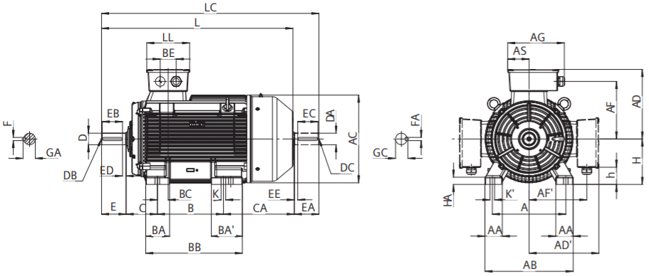
Type of construction IM B35

| Frame size | Type 1LE0001- | Poles | Dimension designation according to IEC standards | ||||||||||||||
|---|---|---|---|---|---|---|---|---|---|---|---|---|---|---|---|---|---|
| A | AA | AB | AC1) | AD / AD' | AF / AF' | AG | AH | AS | B2) | BA / BA' | BB | BC | BE | C | |||
| 80M | 0D×20D×20D×3 | 24, 62, 4, 6 | 125125125 | 363636 | 160160160 | 157157157 | 142142142 | 110.5110.5110.5 | 145145145 | --- | 65.565.565.5 | 100100100 | 444444 | 135135135 | 262626 | 424242 | 505050 |
| 90S | 0E×0 | 2, 4, 6 | 140 | 46 | 175 | 175 | 152 | 120.5 | 145 | - | 65.5 | 100 | 46 | 140 | 20 | 42 | 56 |
| 90L | 0E×4 | 140 | 46 | 175 | 175 | 152 | 120.5 | 145 | - | 65.5 | 125 | 46 | 165 | 20 | 42 | 56 | |
| 100L | 1A×41A×5 | 2, 4, 64 | 160160 | 4545 | 200200 | 196196 | 177177 | 140140 | 163163 | 276276 | 7070 | 140140 | 4545 | 176176 | 30.530.5 | 5454 | 63/783)63/783) |
| 112M | 1B×2 | 2, 4, 6 | 190 | 45 | 226 | 221 | 188.5 | 152 | 163 | 304 | 70 | 140 | 50 | 180 | 22 | 54 | 70 |
| 132S | 1C×0 | 2, 4, 6, 8 | 216 | 50 | 256 | 259 | 212 | 175 | 163 | 354 | 70 | 140 | 64 | 186 | 32.5 | 54 | 89/1043) |
| 1C×1 | 2 | 216 | 50 | 256 | 259 | 212 | 175 | 163 | 354 | 70 | 140 | 64 | 186 | 32.5 | 54 | 89/1043) | |
| 132M | 1C×2 | 4, 6, 8 | 216 | 50 | 256 | 259 | 212 | 175 | 163 | 354 | 70 | 178 | 64 | 224 | 32.5 | 54 | 89/1113) |
| 1C×3 | 6, 8 | 216 | 50 | 256 | 259 | 212 | 175 | 163 | 354 | 70 | 178 | 64 | 224 | 32.5 | 54 | 89/1113) | |
Note:
1) Measured across the bolt heads.
2) This dimension is assigned in DIN EN 50347 to the frame size listed. 3) Only for the motor configured with H08 option.
Type of construction IM B5 and IM V1
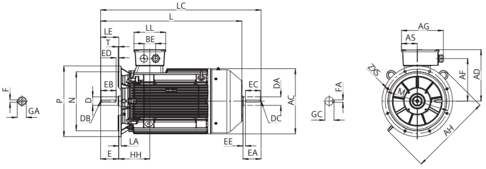
Type of construction IM B14
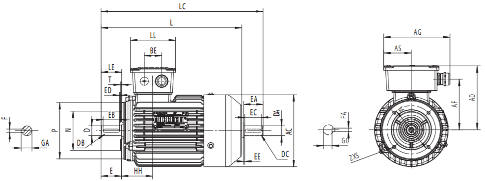
| Dimension designation according to IEC standards | DE shaft extensiion | L05)NDE shaft extension (option code L05) | |||||||||||||||||||||
|---|---|---|---|---|---|---|---|---|---|---|---|---|---|---|---|---|---|---|---|---|---|---|---|
| CA2) | H | h | HA | HH | K / K' | L | LC | LL | D | DB | E | EB | ED | F | GA | DA | DC | EA | EC | EE | FA | GC | |
| 103 | 80 | 14.5 | 10 | 76 | 10 | 288 | 323 | 109 | 19 | M6 | 40 | 32 | 4 | 6 | 21.5 | 14 | M5 | 30 | 22 | 4 | 5 | 16 | |
| 103 | 80 | 14.5 | 10 | 76 | 10 | 288 | 323 | 109 | 19 | M6 | 40 | 32 | 4 | 6 | 21.5 | 14 | M5 | 30 | 22 | 4 | 5 | 16 | |
| 103 | 80 | 14.5 | 10 | 76 | 10 | 288 | 323 | 109 | 19 | M6 | 40 | 32 | 4 | 6 | 21.5 | 14 | M5 | 30 | 22 | 4 | 5 | 16 | |
| 115 | 90 | 24.5 | 10 | 76 | 10 | 316 | 361 | 109 | 24 | M8 | 50 | 40 | 5 | 8 | 27 | 19 | M6 | 40 | 32 | 4 | 8 | 21.5 | |
| 115 | 90 | 24.5 | 10 | 76 | 10 | 341 | 386 | 109 | 24 | M8 | 50 | 40 | 5 | 8 | 27 | 19 | M6 | 40 | 32 | 4 | 8 | 21.5 | |
| 133 | 100 | 30 | 12 | 93.5 | 12 | 390 | 446 | 118 | 28 | M10 | 60 | 50 | 5 | 8 | 31 | 24 | M8 | 50 | 40 | 5 | 8 | 27 | |
| 133 | 100 | 30 | 12 | 93.5 | 12 | 390 | 446 | 118 | 28 | M10 | 60 | 50 | 5 | 8 | 31 | 24 | M8 | 50 | 40 | 5 | 8 | 27 | |
| 129.5 | 112 | 42 | 12 | 92 | 12 | 395 | 450 | 118 | 28 | M10 | 60 | 50 | 5 | 8 | 31 | 24 | M8 | 50 | 40 | 5 | 8 | 27 | |
| 178 | 132 | 62 | 15 | 121.5 | 12 | 480 | 547 | 118 | 38 | M12 | 80 | 70 | 5 | 10 | 41 | 28 | M10 | 60 | 50 | 5 | 8 | 31 | |
| 178 | 132 | 62 | 15 | 121.5 | 12 | 480 | 547 | 118 | 38 | M12 | 80 | 70 | 5 | 10 | 41 | 28 | M10 | 60 | 50 | 5 | 8 | 31 | |
| 185 | 132 | 62 | 15 | 121.5 | 12 | 525 | 592 | 118 | 38 | M12 | 80 | 70 | 5 | 10 | 41 | 28 | M10 | 60 | 50 | 5 | 8 | 31 | |
| 185 | 132 | 62 | 15 | 121.5 | 12 | 525 | 592 | 118 | 38 | M12 | 80 | 70 | 5 | 10 | 41 | 28 | M10 | 60 | 50 | 5 | 8 | 31 | |
Note: 2) This dimension is assigned in DIN EN 50347 to the frame size listed.
| Frame size | Type 1LE0001- | Poles | Dimension designation according to IEC standards | ||||||||||||||
| A | AA | AB | AC1) | AD / AD' | AF / AF' | AG | AH | AS | B2) | BA / BA' | BB | BC | BE | C | |||
| 160M | 1D×21D×3 | 2, 4, 6, 82 | 254254 | 6060 | 314314 | 312312 | 255255 | 206206 | 231231 | 422422 | 9494 | 210210 | 7070 | 258258 | 5151 | 6868 | 108/1123) 108/1123) |
| 160L | 1D×4 | 2, 4, 6, 8 | 254 | 60 | 314 | 312 | 255 | 206 | 231 | 422 | 94 | 254 | 70 | 302 | 51 | 68 | 108//1283) |
| 180M180L | 1E×21E×4 | 2, 44, 6, 8 | 279279 | 6565 | 339339 | 356356 | 270270 | 221221 | 231231 | 466466 | 9494 | 241279 | 8080 | 301339 | 3737 | 6868 | 121/1153) 121/1123) |
| 200L | 2A×42A×5 | 2, 4, 6, 82,6 | 318318 | 7070 | 378378 | 397397 | 300300 | 247.5247.5 | 288288 | 532532 | 107.5107.5 | 305305 | 8080 | 369369 | 6969 | 8585 | 133/1233) 133/1233) |
| 225S225M | 2B×02B×2 | 424, 6, 8 | 356356 | 8080 | 436436 | 442442 | 327327 | 274274 | 288288 | 556556 | 107.5107.5 | 286311 | 8080 | 348373 | 6363 | 8585 | 149/1363) 149/1363) |
| 250M | 2C×2 | 24, 6, 8 | 418(406*) | 90 | 490 | 485 | 375 | 310 | 342 | 600 | 123 | 349 | 100 | 421 | 92 | 84 | 168/1583) |
| 280S 280M | 2D×0 2D×2 | 24, 6, 824, 6, 8 | 457 457 | 100 100 | 540 540 | 535 535 | 420 420 | 355 355 | 342 342 | 652 652 | 123 123 | 368 419 | 115 115 | 454 505 | 72 72 | 84 84 | 190/1573) 190/1573) |
| 315S 315M 315L | 3A×0 3A×2 3A×5/3A×6/3A×7 | 24, 6, 824, 6, 824, 6, 8 | 508 508 508 | 120 120 120 | 610 610 610 | 608 608 608 | 482 482 482 | 401 401 401 | 401 401 401 | 734 734 734 | 148 148 148 | 406 457/508 457/508 | 165 165 165 | 520 668 668 | 75 75 75 | 110 110 110 | 216/1803) 216/3093) 216/2583) |
| 355M | 3B×2 3B×3 3B×4 | 24, 6, 824, 6, 86, 8 | 610 610 610 | 120 120 120 | 730 730 730 | 694 694 694 | 646 646 646 | 545 545 545 | 464 464 464 | 920 920 920 | 175 175 175 | 560/630 560/630 560/630 | 153/207 153/207 153/207 | 750 750 750 | 27 27 27 | 130 130 130 | 254/378 254/378 254/378 |
| 355L | 3B×5 3B×6 | 24, 6, 824, 6, 8 | 610 610 | 120 120 | 730 730 | 694 694 | 646 646 | 545 545 | 464 464 | 920 920 | 175 175 | 560/630 560/630 | 153/207 153/207 | 750 750 | 27 27 | 130 130 | 254/308 254/308 |
Note: 1) Measured across the bolt heads. 2) This dimension is assigned in DIN EN 50347 to the frame size listed. 3) Only for the motor configured with H08 option. * Only applicable for the construction type IM B6, IM B7, IM B8,IM V5,IM V6,IM V15 and IM V35.
| Dimension designation according to IEC standards | DE shaft extensiion | L05)NDE shaft extension (option code L05) | |||||||||||||||||||||
|---|---|---|---|---|---|---|---|---|---|---|---|---|---|---|---|---|---|---|---|---|---|---|---|
| CA2) | H | h | HA | HH | K / K' | L | LC | LL | D | DB | E | EB | ED | F | GA | DA | DC | EA | EC | EE | FA | GC | |
| 194 | 160 | 66 | 20 | 159 | 15 | 614 | 701 | 158 | 42 | M16 | 110 | 100 | 5 | 12 | 45 | 38 | M12 | 80 | 70 | 5 | 10 | 41 | |
| 194 | 160 | 66 | 20 | 159 | 15 | 614 | 701 | 158 | 42 | M16 | 110 | 100 | 5 | 12 | 45 | 38 | M12 | 80 | 70 | 5 | 10 | 41 | |
| 210 | 160 | 66 | 20 | 159 | 15 | 674 | 761 | 158 | 42 | M16 | 110 | 100 | 5 | 12 | 45 | 38 | M12 | 80 | 70 | 5 | 10 | 41 | |
| 219 | 180 | 86 | 20 | 158 | 15 | 683 | 801 | 158 | 48 | M16 | 110 | 100 | 5 | 14 | 51.5 | 42 | M16 | 110 | 90 | 15 | 12 | 45 | |
| 216 | 180 | 86 | 20 | 158 | 15 | 718 | 836 | 158 | 48 | M16 | 110 | 100 | 5 | 14 | 51.5 | 42 | M16 | 110 | 90 | 15 | 12 | 45 | |
| 234 | 200 | 64.5 | 25 | 202 | 19 | 772 | 892 | 215 | 55 | M20 | 110 | 100 | 5 | 16 | 59 | 48 | M16 | 110 | 100 | 5 | 14 | 51.5 | |
| 234 | 200 | 64.5 | 25 | 202 | 19 | 772 | 892 | 215 | 55 | M20 | 110 | 100 | 5 | 16 | 59 | 48 | M16 | 110 | 100 | 5 | 14 | 51.5 | |
| 255 | 225 | 89.5 | 34 | 212 | 19 | 820 | 940 | 215 | 60 | M20 | 140 | 125 | 10 | 18 | 64 | 55 | M20 | 110 | 100 | 5 | 16 | 59 | |
| 255 | 225 | 89.5 | 34 | 212 | 19 | 815 | 935 | 215 | 55 | M20 | 110 | 100 | 5 | 16 | 59 | 48 | M16 | 110 | 100 | 5 | 14 | 51.5 | |
| 845 | 965 | 60 | 140 | 125 | 10 | 18 | 64 | 55 | M20 | 110 | 100 | 5 | 16 | 59 | |||||||||
| 163 | 250 | 81 | 40 | 260 | 24/40 | 820 | 940(1037*) | 246 | 60 | M20 | 140 | 125 | 10 | 18 | 64 | 55 | M20 | 110 | 100 | 5 | 16 | 59 | |
| (269*) | (24*) | (917*) | 970(1067*) | 65 | 69 | 60 | M20 | 140 | 125 | 10 | 18 | 64 | |||||||||||
| 161 | 280 | 111 | 40 | 262 | 24/40 | 900 | 1050 | 246 | 65 | M20 | 140 | 125 | 10 | 18 | 69 | 60 | M20 | 140 | 125 | 10 | 18 | 64 | |
| 75 | 10 | 20 | 79.5 | 65 | M20 | 140 | 125 | 10 | 18 | 69 | |||||||||||||
| 288 | 280 | 111 | 40 | 262 | 24 | 1027 | 1177 | 246 | 65 | M20 | 140 | 125 | 10 | 18 | 69 | 60 | M20 | 140 | 125 | 10 | 18 | 64 | |
| 75 | 20 | 79.5 | 65 | M20 | 140 | 125 | 10 | 18 | 69 | ||||||||||||||
| 351 | 315 | 111 | 50 | 291 | 28 | 1113 | 1265 | 296 | 65 | M20 | 140 | 125 | 10 | 18 | 69 | 65 | M20 | 140 | 125 | 10 | 18 | 69 | |
| 1143 | 1295 | 80 | 170 | 140 | 25 | 22 | 85 | 75 | M20 | 140 | 125 | 10 | 20 | 79.5 | |||||||||
| 480 | 315 | 111 | 50 | 291 | 28 | 1293 | 1445 | 296 | 65 | M20 | 140 | 125 | 10 | 18 | 69 | 65 | M20 | 140 | 125 | 10 | 18 | 69 | |
| 1323 | 1475 | 80 | 170 | 140 | 25 | 22 | 85 | 75 | M20 | 140 | 125 | 10 | 20 | 79.5 | |||||||||
| 480 | 315 | 111 | 50 | 291 | 28 | 1293 | 1445 | 296 | 65 | M20 | 140 | 125 | 10 | 18 | 69 | 65 | M20 | 140 | 125 | 10 | 18 | 69 | |
| 1323 | 1475 | 80 | 170 | 140 | 25 | 22 | 85 | 75 | M20 | 140 | 125 | 10 | 20 | 79.5 | |||||||||
| 547 | 355 | 132.0 | 53 | 281 | 28 | 1490 | 1642 | 347 | 75 | M20 | 140 | 125 | 10 | 20 | 79.5 | 65 | M20 | 140 | 125 | 10 | 18 | 69 | |
| 1520 | 1702 | 95 | M24 | 170 | 140 | 25 | 25 | 100 | 80 | M20 | 170 | 140 | 25 | 22 | 85 | ||||||||
| 547 | 355 | 132.0 | 53 | 281 | 28 | 1490 | 1642 | 347 | 75 | M20 | 140 | 125 | 10 | 20 | 79.5 | 65 | M20 | 140 | 125 | 10 | 18 | 69 | |
| 1520 | 1702 | 95 | M24 | 170 | 140 | 25 | 25 | 100 | 80 | M20 | 170 | 140 | 25 | 22 | 85 | ||||||||
| 547 | 355 | 132.0 | 53 | 281 | 28 | 1520 | 1702 | 347 | 95 | M24 | 170 | 140 | 25 | 25 | 100 | 80 | M20 | 170 | 140 | 25 | 22 | 85 | |
| 547 | 355 | 132.0 | 53 | 281 | 28 | 1490 | 1642 | 347 | 75 | M20 | 140 | 125 | 10 | 20 | 79.5 | 65 | M20 | 140 | 125 | 10 | 18 | 69 | |
| 1520 | 1702 | 95 | M24 | 170 | 140 | 25 | 25 | 100 | 80 | M20 | 170 | 140 | 25 | 22 | 85 | ||||||||
| 547 | 355 | 132.0 | 53 | 281 | 28 | 1490 | 1642 | 347 | 75 | M20 | 140 | 125 | 10 | 20 | 79.5 | 65 | M20 | 140 | 125 | 10 | 18 | 69 | |
| 1520 | 1702 | 95 | M24 | 170 | 140 | 25 | 25 | 100 | 80 | M20 | 170 | 140 | 25 | 22 | 85 | ||||||||
Note: * * Only applicable for the construction type IM B6, IM B7, IM B8,IM V5,IM V6,IM V15 and IM V35.
Type of construction IM B3
Type of construction IM B35
| Frame size | Type 1LE0003- | poles | Dimension designation according to IEC standards | ||||||||||||||||
|---|---|---|---|---|---|---|---|---|---|---|---|---|---|---|---|---|---|---|---|
| A | AA | AB | AC1) | AD / AD' | A F / AF' | AG | AH | AS | B2) | B A / BA' | BB | BC | BE | C | CA2) | H | |||
| 80 M | 0D × 2 | 2 | 125 | 36 | 160 | 166 | 142 | 110.5 | 145 | - | 65.5 | 100 | 44 | 135 | 26 | 42 | 50/903) | 143 | 80 |
| 0D × 2 | 4, 6 | 125 | 36 | 160 | 166 | 142 | 110.5 | 145 | - | 65.5 | 100 | 44 | 135 | 26 | 42 | 50/903) | 143 | 80 | |
| 0D × 3 | 2,4, 6 | 125 | 36 | 160 | 166 | 142 | 110.5 | 145 | - | 65.5 | 100 | 44 | 135 | 26 | 42 | 50/903) | 143 | 80 | |
| 90 S | 0E × 0 | 2, 4, 6 | 140 | 46 | 175 | 184 | 152 | 120.5 | 145 | - | 65.5 | 100 | 46 | 140 | 20 | 42 | 56/1063) | 165 | 90 |
| 90 L | 0E × 4 | 140 | 46 | 175 | 184 | 152 | 120.5 | 145 | - | 65.5 | 125 | 46 | 165 | 20 | 42 | 56/1063) | 165 | 90 | |
| 100 L | 1A × 4 | 2, 4, 6 | 160 | 45 | 200 | 205 | 177 | 140 | 163 | 276 | 70 | 140 | 45 | 176 | 30.5 | 54 | 63/1483) | 203.5 | 100 |
| 1A × 5 | 4 | 160 | 45 | 200 | 205 | 177 | 140 | 163 | 276 | 70 | 140 | 45 | 176 | 30.5 | 54 | 63/1483) | 203.5 | 100 | |
| 112 M | 1B × 2 | 2, 4, 6 | 190 | 45 | 226 | 230 | 188.5 | 152 | 163 | 304 | 70 | 140 | 50 | 180 | 22 | 54 | 70/1253) | 182 | 112 |
| 132 S | 1C × 0 | 2, 4, 6 | 216 | 50 | 256 | 268 | 212 | 175 | 163 | 354 | 70 | 140 | 64 | 186 | 32.5 | 54 | 89/1393) | 213 | 132 |
| 1 × 1 | 2 | 216 | 50 | 256 | 268 | 212 | 175 | 163 | 354 | 70 | 140 | 64 | 186 | 32.5 | 54 | 89/1393) | 213 | 132 | |
| 132 M | 1C × 2 | 4, 6 | 216 | 50 | 256 | 268 | 212 | 175 | 163 | 354 | 70 | 178 | 64 | 224 | 32.5 | 54 | 89/1463) | 220 | 132 |
| 1C × 3 | 6 | 216 | 50 | 256 | 268 | 212 | 175 | 163 | 354 | 70 | 178 | 64 | 224 | 32.5 | 54 | 89/1463) | 220 | 132 | |
| 160 M | 1D × 2 | 2, 4, 6 | 254 | 60 | 314 | 324 | 255 | 206 | 231 | 422 | 94 | 210 | 70 | 258 | 51 | 68 | 108/1123) | 193 | 160 |
| 1D × 3 | 2 | 254 | 60 | 314 | 324 | 255 | 206 | 231 | 422 | 94 | 210 | 70 | 258 | 51 | 68 | 108/1123) | 193 | 160 | |
| 160 L | 1D × 4 | 2, 4, 6 | 254 | 60 | 314 | 324 | 255 | 206 | 231 | 422 | 94 | 254 | 70 | 302 | 51 | 68 | 108/1283) | 209 | 160 |
Note: 1) Measured across the bolt heads. 2) This dimension is assigned in DIN EN 50347 to the frame size listed. 3) Only for the motor configured with H08 option
Type of construction IM B5 and IM V1
Type of construction IM B14
| Dimension designation according to IEC standards | DE shaft extensiion | L05)NDE shaft extension (option code L05) | |||||||||||||||||||
|---|---|---|---|---|---|---|---|---|---|---|---|---|---|---|---|---|---|---|---|---|---|
| h | HA | HH | K / K' | L | LC | LL | D | DB | E | EB | ED | F | GA | DA | DC | EA | EC | EE | FA | GC | |
| 14.5 | 10 | 76 | 10 | 328 | 363 | 109 | 19 | M6 | 40 | 32 | 4 | 6 | 21.5 | 14 | M5 | 30 | 22 | 4 | 5 | 16 | |
| 14.5 | 10 | 76 | 10 | 328 | 363 | 109 | 19 | M6 | 40 | 32 | 4 | 6 | 21.5 | 14 | M5 | 30 | 22 | 4 | 5 | 16 | |
| 14.5 | 10 | 76 | 10 | 328 | 363 | 109 | 19 | M6 | 40 | 32 | 4 | 6 | 21.5 | 14 | M5 | 30 | 22 | 4 | 5 | 16 | |
| 24.5 | 10 | 76 | 10 | 366 | 411 | 109 | 24 | M8 | 50 | 40 | 5 | 8 | 27 | 19 | M6 | 40 | 32 | 5 | 8 | 21.5 | |
| 24.5 | 10 | 76 | 10 | 391 | 436 | 109 | 24 | M8 | 50 | 40 | 5 | 8 | 27 | 19 | M6 | 40 | 32 | 5 | 8 | 21.5 | |
| 30 | 12 | 93.5 | 12 | 460 | 516.5 | 118 | 28 | M10 | 60 | 50 | 5 | 8 | 31 | 24 | M8 | 50 | 40 | 5 | 8 | 27 | |
| 30 | 12 | 93.5 | 12 | 460 | 516.5 | 118 | 28 | M10 | 60 | 50 | 5 | 8 | 31 | 24 | M8 | 50 | 40 | 5 | 8 | 27 | |
| 42 | 12 | 92 | 12 | 448 | 504.5 | 118 | 28 | M10 | 60 | 50 | 5 | 8 | 31 | 24 | M8 | 50 | 40 | 5 | 8 | 27 | |
| 62 | 15 | 121.5 | 12 | 515 | 582 | 118 | 38 | M12 | 80 | 70 | 5 | 10 | 41 | 28 | M10 | 60 | 50 | 5 | 8 | 31 | |
| 62 | 15 | 121.5 | 12 | 515 | 582 | 118 | 38 | M12 | 80 | 70 | 5 | 10 | 41 | 28 | M10 | 60 | 50 | 5 | 8 | 31 | |
| 62 | 15 | 121.5 | 12 | 560 | 627 | 118 | 38 | M12 | 80 | 70 | 5 | 10 | 41 | 28 | M10 | 60 | 50 | 5 | 8 | 31 | |
| 62 | 15 | 121.5 | 12 | 560 | 627 | 118 | 38 | M12 | 80 | 70 | 5 | 10 | 41 | 28 | M10 | 60 | 50 | 5 | 8 | 31 | |
| 66 | 20 | 159 | 15 | 614 | 701 | 158 | 42 | M16 | 110 | 100 | 5 | 12 | 45 | 38 | M12 | 80 | 70 | 5 | 10 | 41 | |
| 66 | 20 | 159 | 15 | 614 | 701 | 158 | 42 | M16 | 110 | 100 | 5 | 12 | 45 | 38 | M12 | 80 | 70 | 5 | 10 | 41 | |
| 66 | 20 | 159 | 15 | 674 | 761 | 158 | 42 | M16 | 110 | 100 | 5 | 12 | 45 | 38 | M12 | 80 | 70 | 5 | 10 | 41 | |
Note: 1) Measured across the bolt heads. 2) This dimension is assigned in DIN EN 50347 to the frame size listed. 3) Only for the motor configured with H08 option
Type of construction IM B3
Type of construction IM B35
| Frame size | Type 1LE0003- | poles | Dimension designation according to IEC standards | ||||||||||||||
|---|---|---|---|---|---|---|---|---|---|---|---|---|---|---|---|---|---|
| A | AA | AB | AC1) | AD / AD' | AF / AF' | AG | AH | AS | B2) | BA / BA' | BB | BC | BE | C | |||
| 180M180L | 1E × 21E × 4 | 2,44,6 | 279279 | 6565 | 339339 | 368368 | 270270 | 221221 | 231231 | 466466 | 9494 | 241279 | 8080 | 301339 | 3737 | 6868 | 121/1503)121/1523) |
| 200L | 2A × 42A × 5 | 2,4,62,6 | 318318 | 7070 | 378378 | 409409 | 300300 | 247.5247.5 | 288288 | 532532 | 107.5107.5 | 305305 | 8080 | 369369 | 6969 | 8585 | 133/1583)133/1583) |
| 225S | 2B × 0 | 4 | 356 | 80 | 436 | 457 | 327 | 274 | 288 | 556 | 107.5 | 286 | 90 | 348 | 63 | 85 | 149/1363) |
| 225M | 2B × 2 | 2 | 356 | 80 | 436 | 457 | 327 | 274 | 288 | 556 | 107.5 | 311 | 90 | 373 | 63 | 85 | 149/1663) |
| 4, 6 | |||||||||||||||||
| 250M | 2C × 2 | 24, 6 | 406 | 90 | 490 | 503 | 373 | 310.5 | 342 | 600 | 123 | 349 | 100 | 421 | 92 | 84 | 168/2083) |
| 280S | 2D × 0 | 2 | 457 | 100 | 540 | 553 | 413 | 350.5 | 342 | 652 | 123 | 368 | 115 | 454 | 72 | 84 | 190/1723) |
| 4, 6 | |||||||||||||||||
| 280M | 2D × 2 | 2 | 457 | 100 | 540 | 553 | 413 | 350.5 | 342 | 652 | 123 | 419 | 115 | 505 | 72 | 84 | 190/1723) |
| 4, 6 | |||||||||||||||||
| 315S | 3A × 0 | 2 | 508 | 120 | 610 | 623 | 482 | 401 | 401 | 734 | 148 | 406 | 140 | 520 | 75 | 110 | 216/2303) |
| 4, 6 | |||||||||||||||||
| 315M | 3A × 2 | 2 | 508 | 120 | 610 | 623 | 482 | 401 | 401 | 734 | 148 | 457/508 | 165/215 | 668 | 75 | 110 | 216/4093) |
| 4, 6 | |||||||||||||||||
| 315L | 3A × 5/3A × 6/3A × 7 | 2 | 508 | 120 | 610 | 623 | 482 | 401 | 401 | 734 | 148 | 457/508 | 165/215 | 668 | 75 | 110 | 216/3583) |
| 4, 6 | |||||||||||||||||
| 3B × 2 | 2 | 610 | 120 | 730 | 710 | 646 | 545 | 464 | 920 | 173.5 | 560/630 | 153/207 | 750 | 27 | 130 | 254/3783) | |
| 4, 6 | |||||||||||||||||
| 355M | 3B × 2 | 2 | 610 | 120 | 730 | 710 | 646 | 545 | 464 | 920 | 173.5 | 560/630 | 153/207 | 750 | 27 | 130 | 254/3783) |
| 4, 6 | |||||||||||||||||
| 3B × 4 | 6, | 610 | 120 | 730 | 710 | 646 | 545 | 464 | 920 | 173.5 | 560/630 | 153/207 | 750 | 27 | 130 | 254/3783) | |
| 355L | 3B × 53B × 6 | 24, 624, 6 | 610610 | 120120 | 730730 | 710710 | 646646 | 545545 | 464464 | 920920 | 173.5173.5 | 560/630560/630 | 153/207153/207 | 750750 | 2727 | 130130 | 254/3083)254/3083) |
Note: 1) Measured across the bolt heads. 2) This dimension is assigned in DIN EN 50347 to the frame size listed. 3) Only for the motor configured with H08 option
Type of construction IM B5
| Dimension designation according to IEC standards | DE shaft extensiion | L05)NDE shaft extension (option code L05) | |||||||||||||||||||||
|---|---|---|---|---|---|---|---|---|---|---|---|---|---|---|---|---|---|---|---|---|---|---|---|
| CA2) | H | h | HA | HH | K / K' | L | LC | LL | D | DB | E | EB | ED | F | GA | DA | DC | EA | EC | EE | FA | GC | |
| 254 | 180 | 86 | 20 | 158 | 15 | 718 | 836 | 158 | 48 | M16 | 110 | 100 | 5 | 14 | 51.5 | 42 | M16 | 110 | 90 | 10 | 12 | 45 | |
| 256 | 180 | 86 | 20 | 158 | 15 | 758 | 876 | 158 | 48 | M16 | 110 | 100 | 5 | 14 | 51.5 | 42 | M16 | 110 | 90 | 10 | 12 | 45 | |
| 269 | 200 | 64.5 | 25 | 202 | 19 | 807 | 927 | 215 | 55 | M20 | 110 | 100 | 5 | 16 | 59 | 48 | M16 | 110 | 100 | 5 | 14 | 51.5 | |
| 269 | 200 | 64.5 | 25 | 202 | 19 | 807 | 927 | 215 | 55 | M20 | 110 | 100 | 5 | 16 | 59 | 48 | M16 | 110 | 100 | 5 | 14 | 51.5 | |
| 280 | 225 | 89.5 | 34 | 212 | 19 | 845 | 965 | 215 | 60 | M20 | 140 | 125 | 10 | 18 | 64 | 55 | M20 | 110 | 100 | 5 | 16 | 59 | |
| 260 | 225 | 89.5 | 34 | 212 | 19 | 820 | 940 | 215 | 55 | M20 | 110 | 100 | 5 | 16 | 59 | 48 | M16 | 110 | 100 | 5 | 14 | 51.5 | |
| 285 | 875 | 995 | 60 | 140 | 125 | 10 | 18 | 64 | 55 | M20 | 110 | 100 | 5 | 16 | 59 | ||||||||
| 320 | 250 | 81 | 40 | 260 | 24 | 965 | 1087 | 246 | 60 | M20 | 140 | 125 | 10 | 18 | 64 | 55 | M20 | 110 | 100 | 5 | 16 | 59 | |
| 1117 | 65 | 69 | 60 | M20 | 140 | 125 | 10 | 18 | 64 | ||||||||||||||
| 303 | 280 | 111 | 40 | 262 | 24 | 991 | 1141 | 246 | 65 | M20 | 140 | 125 | 10 | 18 | 69 | 60 | M20 | 140 | 125 | 10 | 18 | 64 | |
| 303 | 75 | 10 | 20 | 79.5 | 65 | M20 | 140 | 125 | 10 | 18 | 69 | ||||||||||||
| 303 | 280 | 111 | 40 | 262 | 24 | 1042 | 1192 | 246 | 65 | M20 | 140 | 125 | 10 | 18 | 69 | 60 | M20 | 140 | 125 | 10 | 18 | 64 | |
| 75 | 20 | 79.5 | 65 | M20 | 140 | 125 | 10 | 18 | 69 | ||||||||||||||
| 413 | 315 | 111 | 50 | 291 | 28 | 1163 | 1315 | 296 | 65 | M20 | 140 | 125 | 10 | 18 | 69 | 65 | M20 | 140 | 125 | 10 | 18 | 69 | |
| 613 | 1193 | 1545 | 80 | 170 | 140 | 25 | 22 | 85 | 75 | M20 | 140 | 125 | 10 | 20 | 79.5 | ||||||||
| 392/341 | 315 | 111 | 50 | 291 | 28 | 1393 | 1345 | 296 | 65 | M20 | 140 | 125 | 10 | 18 | 69 | 65 | M20 | 140 | 125 | 10 | 18 | 69 | |
| 592/541 | 1423 | 1575 | 80 | 170 | 140 | 25 | 22 | 85 | 75 | M20 | 140 | 125 | 10 | 20 | 79.5 | ||||||||
| 392/341 | 315 | 111 | 50 | 291 | 28 | 1393 | 1345 | 296 | 65 | M20 | 140 | 125 | 10 | 18 | 69 | 65 | M20 | 140 | 125 | 10 | 18 | 69 | |
| 592/541 | 1423 | 1575 | 80 | 170 | 140 | 25 | 22 | 85 | 75 | M20 | 140 | 125 | 10 | 20 | 79.5 | ||||||||
| 548/478 | 355 | 132 | 53 | 281 | 28 | 1490 | 1642 | 397 | 75 | M20 | 140 | 125 | 10 | 20 | 79.5 | 65 | M20 | 140 | 125 | 10 | 18 | 69 | |
| 1520 | 1702 | 95 | M24 | 170 | 140 | 25 | 25 | 100 | 80 | M20 | 170 | 140 | 25 | 22 | 85 | ||||||||
| 548/478 | 355 | 132 | 53 | 281 | 28 | 1490 | 1642 | 397 | 75 | M20 | 140 | 125 | 10 | 20 | 79.5 | 65 | M20 | 140 | 125 | 10 | 18 | 69 | |
| 1520 | 1702 | 95 | M24 | 170 | 140 | 25 | 25 | 100 | 80 | M20 | 170 | 140 | 25 | 22 | 85 | ||||||||
| 548/478 | 355 | 132 | 53 | 281 | 28 | 1520 | 1702 | 95 | M24 | 170 | 140 | 25 | 25 | 100 | 80 | M20 | 170 | 140 | 25 | 22 | 85 | ||
| 548/478 | 355 | 132 | 53 | 281 | 28 | 1490 | 1642 | 397 | 75 | M20 | 140 | 125 | 10 | 20 | 79.5 | 65 | M20 | 140 | 125 | 10 | 18 | 69 | |
| 1520 | 1702 | 95 | M24 | 170 | 140 | 25 | 25 | 100 | 80 | M20 | 170 | 140 | 25 | 22 | 85 | ||||||||
| 548/478 | 355 | 132 | 53 | 281 | 28 | 1490 | 1642 | 397 | 75 | M20 | 140 | 125 | 10 | 20 | 79.5 | 65 | M20 | 140 | 125 | 10 | 18 | 69 | |
| 1520 | 1702 | 95 | M24 | 170 | 140 | 25 | 25 | 100 | 80 | M20 | 170 | 140 | 25 | 22 | 85 | ||||||||
Note: 1) Measured across the bolt heads. 2) This dimension is assigned in DIN EN 50347 to the frame size listed. 3) Only for the motor configured with H08 option
Type of construction IM B5, IM B35, IM V1, IM V3
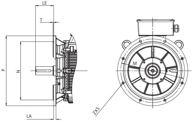
Type of construction IM B14, IM V18, IM V19
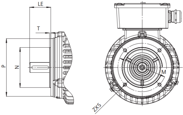
| Frame size | Type of construction | Flange with through holes (FF/A) / tapped holes (FT/C) | Dimension designation according to IEC standards | |||||||
|---|---|---|---|---|---|---|---|---|---|---|
| According to DIN EN 50347 | LA | LE | M | N | P | S | T | Z | ||
| 80 | IM B5, IM B35, IM V1, IM V3IM B14, IM V18, IM V19 | FF 165FT 100 | 10- | 4040 | 165100 | 13080 | 200120 | 12M 6 | 3.53 | 44 |
| 90 | IM B5, IM B35, IM V1, IM V3IM B14, IM V18, IM V19 | FF 165FT 115 | 10- | 5050 | 165115 | 13095 | 200140 | 12M 8 | 3.53 | 44 |
| 100 | IM B5, IM B35, IM V1, IM V3IM B14, IM V18, IM V19 | FF 215FT 130 | 11- | 6060 | 215130 | 180110 | 250160 | 14.5M 8 | 43.5 | 44 |
| 112 | IM B5, IM B35, IM V1, IM V3IM B14, IM V18, IM V19 | FF 215FT 130 | 11- | 6060 | 215130 | 180110 | 250160 | 14.5M 8 | 43.5 | 44 |
| 132 | IM B5, IM B35, IM V1, IM V3IM B14, IM V18, IM V19 | FF 265FT 165 | 14- | 8080 | 265165 | 230130 | 300200 | 14.5M 10 | 43.5 | 44 |
| 160 | IM B5, IM B35, IM V1, IM V3IM B14, IM V18, IM V19 | FF 300FT 215 | 14- | 110110 | 300215 | 250180 | 350250 | 18.5M 12 | 54 | 44 |
| 180 | IM B5, IM B35, IM V1, IM V3 | FF 300 | 16 | 110 | 300 | 250 | 350 | 18.5 | 5 | 4 |
| 200 | IM B5, IM B35, IM V1, IM V3 | FF 350 | 16 | 110 | 350 | 300 | 400 | 18.5 | 5 | 4 |
| 225 | IM B5, IM B35, IM V1, IM V3 | FF 400 | 16 | 110/140 | 400 | 350 | 450 | 18.5 | 5 | 8 |
| 250 | IM B5, IM B35, IM V1, IM V3 | FF 500 | 18 | 140 | 500 | 450 | 550 | 18.5 | 5 | 8 |
| 280 | IM B5, IM B35, IM V1, IM V3 | FF 500 | 18 | 140 | 500 | 450 | 550 | 18.5 | 5 | 8 |
| 315 | IM B5, IM B35, IM V1, IM V3 | FF 600 | 22 | 140/170 | 600 | 550 | 660 | 24 | 6 | 8 |
| 355 | IM B35, IM V1 | FF 740 | 22 | 140/170 | 740 | 680 | 800 | 24 | 6 | 8 |
